
torque transfer device

A technology of torque transmission device and vibration damping device, which is applied in the direction of rigid shaft coupling, elastic coupling, friction clutch, etc., can solve the problem of large connection noise, and achieve the effect of easy installation and disassembly

Inactive Publication Date: 2016-06-22
SCHAEFFLER TECH AG & CO KG
View PDF6 Cites 0 Cited by
  • Summary
  • Abstract
  • Description
  • Claims
  • Application Information

AI Technical Summary

Problems solved by technology

However, this connection is noisy

Method used


Image

  • torque transfer device
  • torque transfer device
  • torque transfer device

Examples


Embodiment Construction

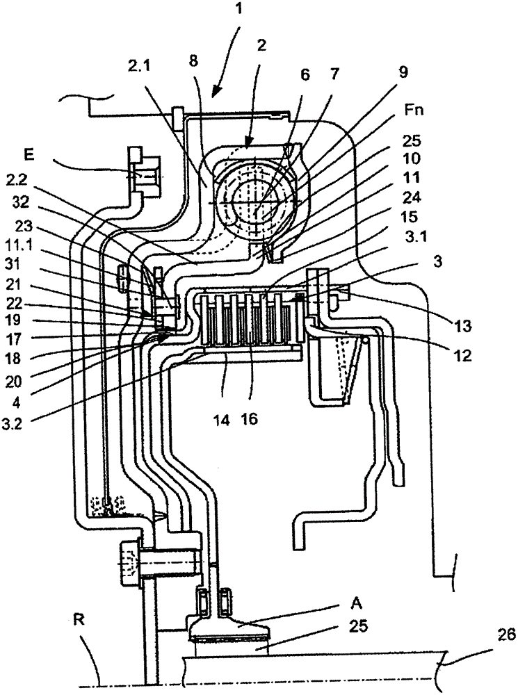
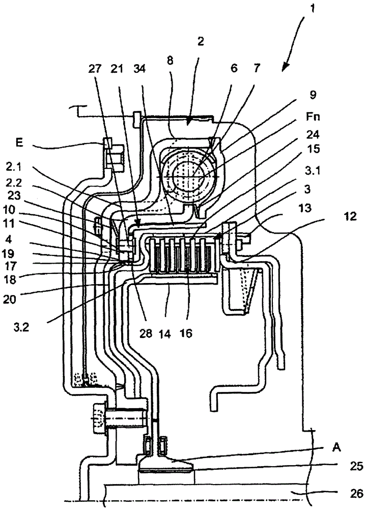
[0028] Figure 1a An example of a non-rotatable connection device 4 between a damper device 2 and a switchable clutch device 3 is shown in an axial section through the torque transmission device 1 according to Clamping device constructed in the present invention. Hatching is not drawn for reasons of clarity.

[0029] The torque transmission device 1 comprises at least one input E and at least one output A, between which at least one clutch device 3 and a damping device 2, also called As a torsional vibration damper. Other functional elements, for example a further switchable clutch device and / or a hydraulic component are also conceivable. For torque transmission, the damper device 2 and the switchable clutch device 3 are connected to one another via a non-rotatable connection device 4 . The damper device 2 and the switchable clutch device 3 are arranged one behind the other along the energy flow. The torque transmission in the main operating range can take place depending ...


PUM


Abstract

The invention relates to a torque transmission device, comprising a vibration-damping device and a switchable coupling mechanism, which are connected to each other via a toothing for conjoint rotation. The invention is characterized in that means for bracing the toothing in the torque transmission direction are provided.

Description

technical field [0001] The invention relates to a torque transmission device comprising a device for damping vibrations and a switchable clutch device, the vibration damping device and the clutch device being non-rotatably connected to one another via a toothing. Background technique [0002] It is known from the prior art that torque transmission devices of this type are mostly in the form of double clutch devices or with integrated hydraulic components, in particular in the form of hydraulic speed / torque converters. The switchable clutch arrangement can be designed as a wet-running multi-plate clutch. [0003] Laid-open document DE 10 2009 024 217 A1 describes the design of a dual clutch arrangement with two wet-running multi-plate clutches and a damper. In this configuration, the vibration damping device is integrated in the torque transmission device, so that components requiring axial installation space can be used together. In this way, an input part and a damper out...

Claims


Application Information

Patent Timeline
Patent Type & Authority Patents(China)
IPC IPC(8): F16D3/12F16D13/70
CPCF16D3/12F16D13/70F16D2001/103
Inventor M·德格勒
Owner SCHAEFFLER TECH AG & CO KG
Learn More