
Optical disk drive

a technology of optical disk drive and assembly structure, which is applied in the direction of information storage, instruments, data recording, etc., can solve the problems of requiring extra space and extra work steps, difficult to achieve compactness and enhance workability, and achieve compactness. , the effect of simplifying components

Inactive Publication Date: 2010-07-13
FUNAI ELECTRIC CO LTD
View PDF9 Cites 0 Cited by
  • Summary
  • Abstract
  • Description
  • Claims
  • Application Information

AI Technical Summary

Benefits of technology

[0009]An object of the present invention is to provide a disc apparatus that can be built with a compact assembly structure of a traverse mechanism and gears, with simplified components, and with enhanced workability.
[0012]According to the present invention, it is possible to realize a disc apparatus that can be built with a simple structure, achieving compactness, simplifying components, and enhancing workability, in particular in terms of the assembly structure of a traverse mechanism and gears.
[0013]Specifically, with a structure where a traverse mechanism has a gear and a shift lever fitted integrally therewith, it is possible to make components compact while preventing the gear from dropping off. Here, by making the gear concentric with the screw with which the shift lever is fitted, it is possible to achieve further compactness. Moreover, since the shift lever can be previously incorporated in the traverse mechanism, it is possible to enhance workability in the assembly line.

Problems solved by technology

Disadvantageously, however, the structures disclosed in the patent publications mentioned above require extra space and extra work steps for fitting cushioning members or vibration-damping members.
This makes it accordingly difficult to achieve compactness and enhance workability.

Method used


Image

  • Optical disk drive
  • Optical disk drive
  • Optical disk drive

Examples


Embodiment Construction

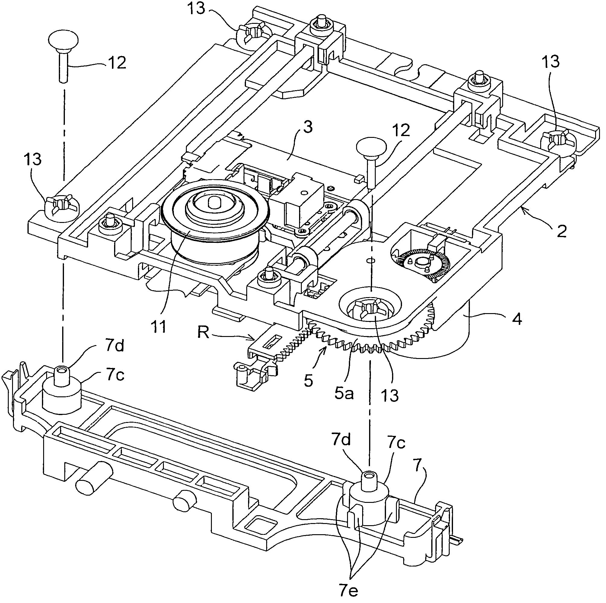
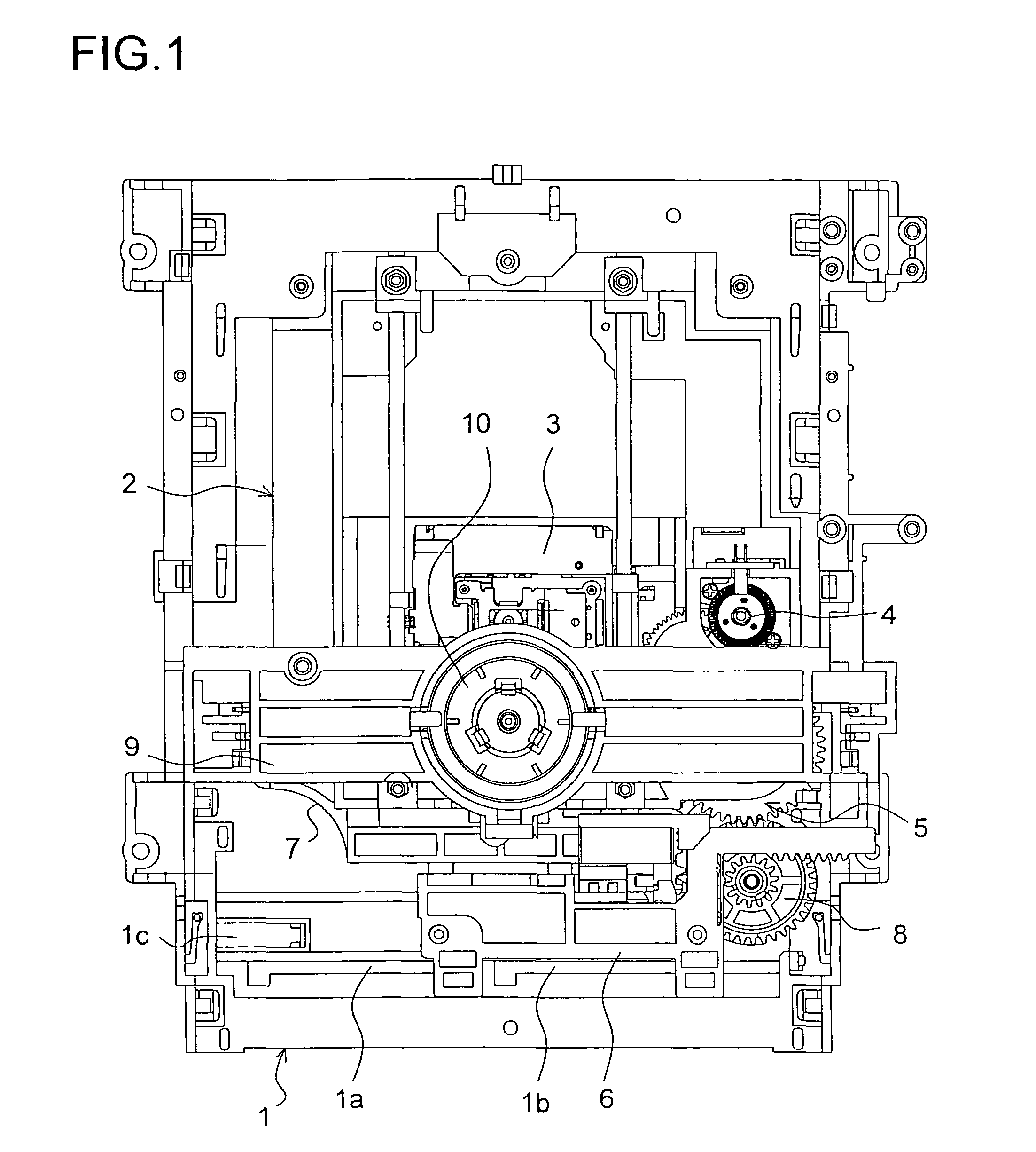
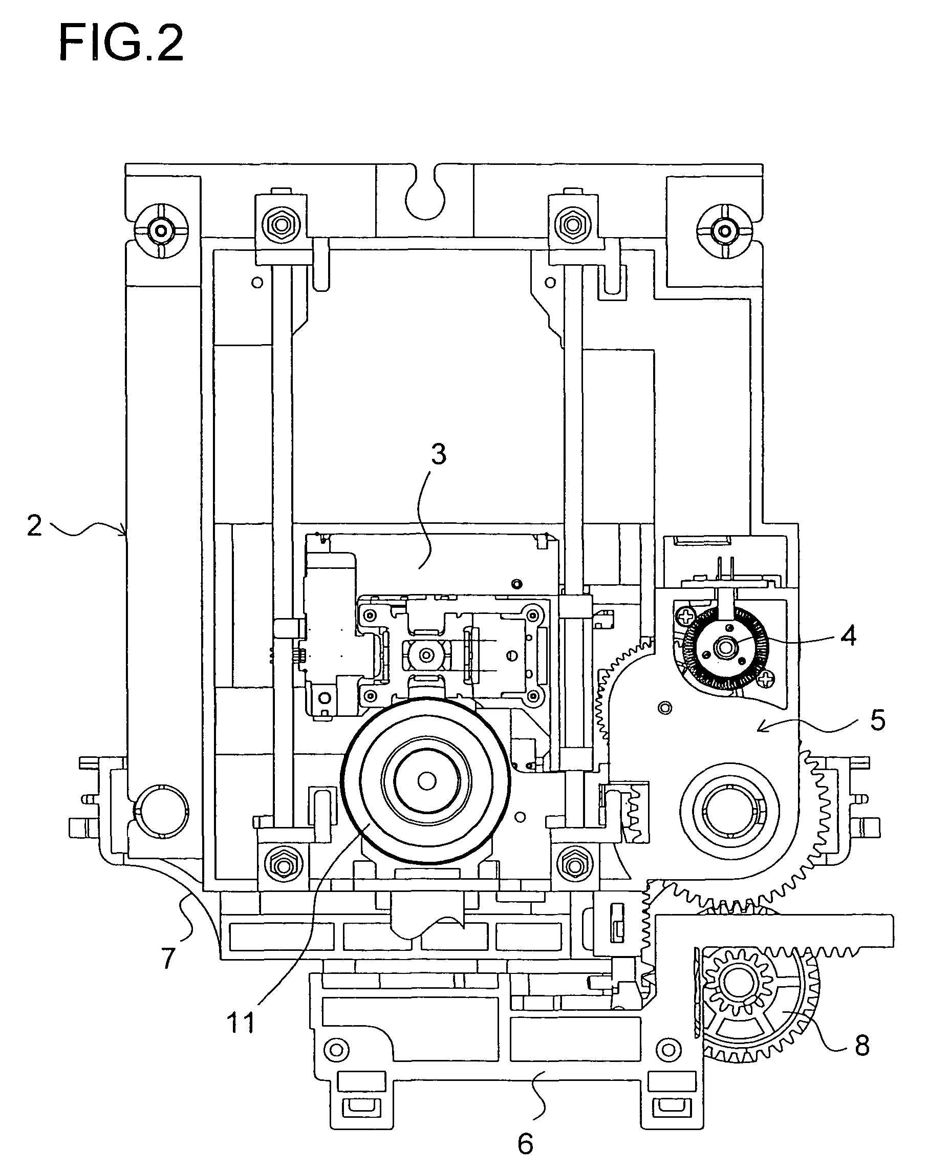
[0019]Hereinafter, an embodiment of the present invention will be described with reference to the accompanying drawings. FIG. 1 is a plan view showing the disc loader of a disc apparatus embodying the present invention, and FIG. 2 is a plan view showing, mainly, the traverse mechanism of the disc apparatus. This disc apparatus has, provided on a loader chassis 1: a tray (unillustrated) that transports a disc-shaped recording medium; and a traverse mechanism 2 that can ascend and descend by pivoting in a direction substantially perpendicular to the transport direction (front / rear direction) of the tray. The loader chassis 1 is fixed to an apparatus cabinet (unillustrated).

[0020]The traverse mechanism 2 is provided with: a pick-up unit 3 having an optical pick-up that records to and plays back from the disk-shaped recording medium; and a motor 4 that moves the pick-up unit 3 in a direction radial to the disk-shaped recording medium. The motor 4 is provided with transmission means 5 co...


PUM

PropertyMeasurementUnit
assembly structureaaaaaaaaaa
workabilityaaaaaaaaaa
structureaaaaaaaaaa

Abstract

When a shift lever is fitted under a front part of a traverse mechanism, dampers have previously been fitted in a total of two, front-left and front-right, parts, called mount parts, of a mechanism chassis. A flat gear rotatably engages with a cylindrical sleeve protruding downward from the front-right mount part of the mechanism chassis. A feed gear in a rear part of transmission means rotatably engages with a boss protruding downward behind the sleeve, and is prevented from dropping off with a screw put from below. Now, the flat gear is, in a rear part thereof, supported by the feed gear, and is thereby prevented from dropping off.

Description

[0001]This application is based on Japanese Patent Application No. 2005-201841 filed on Jul. 11, 2006, the contents of which are hereby incorporated by reference.BACKGROUND OF THE INVENTION[0002]1. Field of the Invention[0003]The present invention relates to a disc apparatus that records to and plays back from a disc-shaped recording medium such as a CD or DVD; more particularly, the present invention relates to an assembly structure of a traverse mechanism and gears.[0004]2. Description of Related Art[0005]One known type of disc apparatus is structured as follows: a disc tray having a disc-shaped recording medium placed thereon is moved into a cabinet, then the disc-shaped recording medium is clamped between a disc holder (clamper) and a turntable, both provided inside the cabinet, and then recording or playback is performed to or from the disc-shaped recording medium. In recent years, various improvements associated with this structure have been proposed with the aims to achieve c...

Claims


Application Information

Patent Timeline
Patent Type & Authority Patents(United States)
IPC IPC(8): G11B7/00
CPCG11B17/0285G11B17/0288
Inventor OKAZAKI, NOBUYUKIHAYASHI, RYUUJI
Owner FUNAI ELECTRIC CO LTD
Learn More