Eureka AIR delivers breakthrough ideas for toughest innovation challenges, trusted by R&D personnel around the world.

Fixation device for stably interlinking at least two bone fragments of a broken bone and corresponding fixation element and kit

a technology of fixation device and bone fragment, which is applied in the direction of non-surgical orthopedic devices, external osteosynthesis, medical science, etc., can solve the problems of low manufacturing cost of component parts, only a relatively low tightening torque, and the effect of tightening for tensioning the connection

Inactive Publication Date: 2012-04-03
TANTUM AG
View PDF18 Cites 46 Cited by
  • Summary
  • Abstract
  • Description
  • Claims
  • Application Information

AI Technical Summary

Benefits of technology

[0006]It is the aim of the invention to design a fixation device in such a way that it is particularly easy to handle and cheaply available with relatively few components, wherein the rigidity of the connection can be guaranteed particularly high and reliable over a long period of time. Nevertheless it should be possible to make the components of the device from lightweight material and cheaply in mass production, in particular from plastic parts made by injection moulding. If necessary, manufacture should be so cheap that the product is usable as a cheap disposable product, in order to simplify the procedures in particular in a hospital by avoiding return, reprocessing and sterilisation of already used fixators.
[0007]The aims of the invention are achieved in conjunction with the features of the fixation device of the kind mentioned hereinbefore by the fact that the clamping holder is lined up on the tensioning rod, comprising a through-opening which is designed in such a way that the tensioning rod passes through the through-opening with sufficient play in the through-opening for spatial guidance of the clamping holder. A number of advantages are gained with the solution of the invention. Due to the three-dimensional guiding of movement and capacity of the clamping holder for displacement, adjustment and connection of the fixation element to fixation rods is particularly simplified and facilitated. Also, this contributes to a particular extent to the rod and base body or clamping bearing not being braced with forces transverse to the tensioning rod in the state of force-locking connection. This increases the strength and stability of the device to a particular extent. With regard to a simple shape, it is particularly advantageous that the clamping holder for the clamping rod forms a bearing which as such is movable as a unit in three dimensions, that is, in all spatial directions. The tensioning rod connection is particularly simple because portions to be clamped including the clamping holder which is guided and displaceable on the base body in all spatial directions are released by one and the same pull rod of the tensioning connection and attached to each other in a rigid connection. Tensioning force is applied uniformly to different parts of the tensioning combination, namely both for fixing the fixation rod in its clamping holder and for fixing the clamping holder of which the angle is spatially adjustable in a bearing element on the base body. The shape of connection and construction according to the invention allows the components to be made relatively simple. The manufacturing costs of the component parts remain low. Compared with traditional devices, the expenditure for component parts is considerably reduced with respect to number, handling and use. In particular, parts to be made by shape cutting chipping technology are avoided, and lightweight components preferably consisting of plastic injection mouldings are used instead.
[0008]A fixation element according to the invention which is particularly universally usable is achieved by the fact that on the tensioning rod are placed in a row at least one base body and on the base body opposite each other two rod clamping holders with their bearing portions. Appropriately, with this design the base body is formed by a cross-shaped element including a cylindrical longitudinal body portion which comprises bearing surfaces at its ends for a clamping holder each, and a transverse body portion which receives at least one bone nail. This shape of the base body, of which the longitudinal body portion has the tensioning rod passing through it, has relatively large resistance cross-sections for compression and / or bending loads, so that the tensioning connection is particularly firm and stable. Appropriately, along the extent of the transverse body portion in the latter is formed a through-slot which receives bone nails in regions of the transverse body portion projecting from the longitudinal body portion. This leads both to a spatially particularly favourable arrangement of the bone nails and a particularly effective and pronounced transmission of tensioning force along the longitudinal body portion. Also the result is that tightening for tensioning the connection is associated with only a relatively low tightening torque.

Problems solved by technology

The manufacturing costs of the component parts remain low.
Also the result is that tightening for tensioning the connection is associated with only a relatively low tightening torque.

Method used


Image

  • Fixation device for stably interlinking at least two bone fragments of a broken bone and corresponding fixation element and kit
  • Fixation device for stably interlinking at least two bone fragments of a broken bone and corresponding fixation element and kit
  • Fixation device for stably interlinking at least two bone fragments of a broken bone and corresponding fixation element and kit

Examples


Embodiment Construction

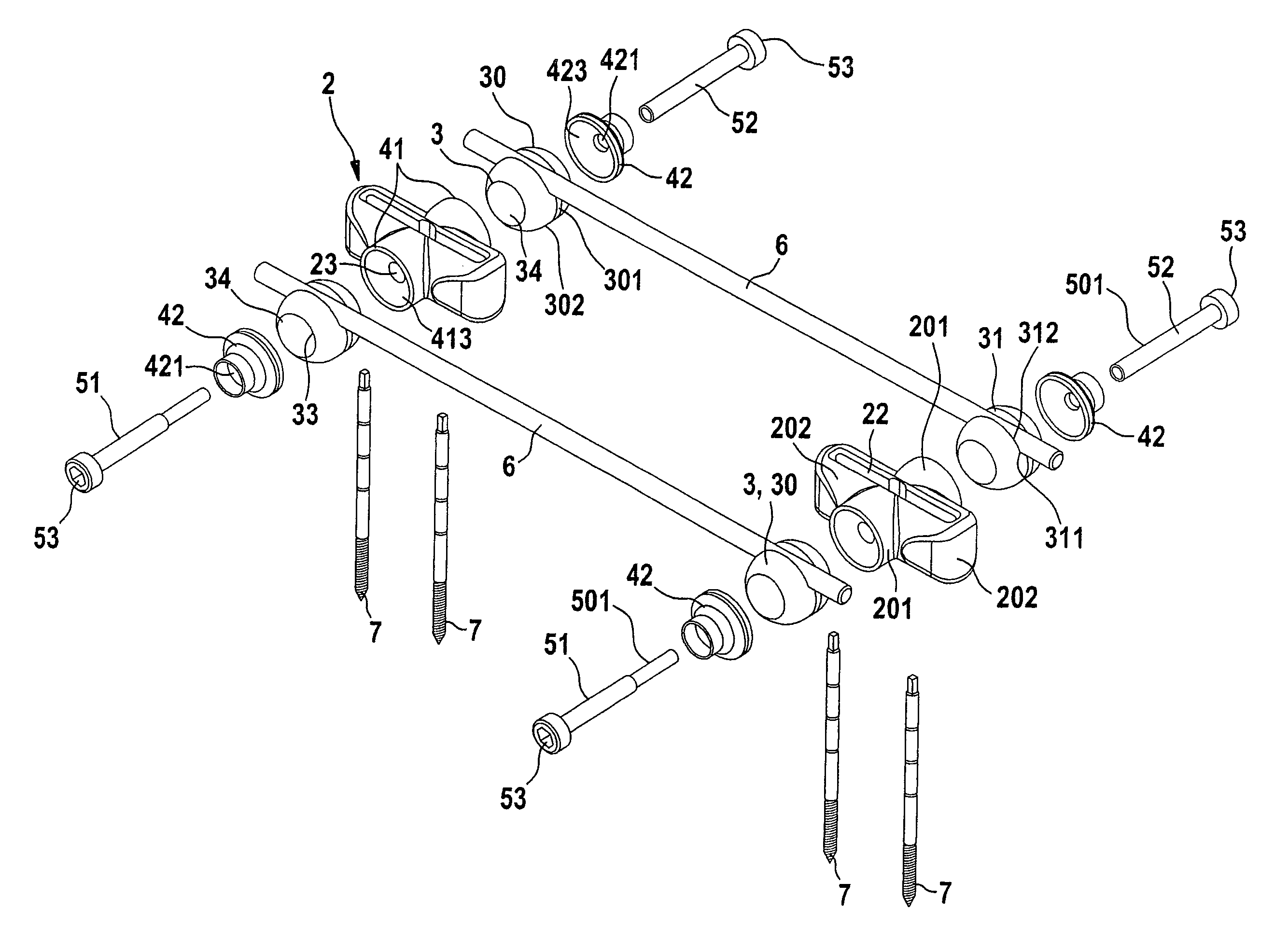
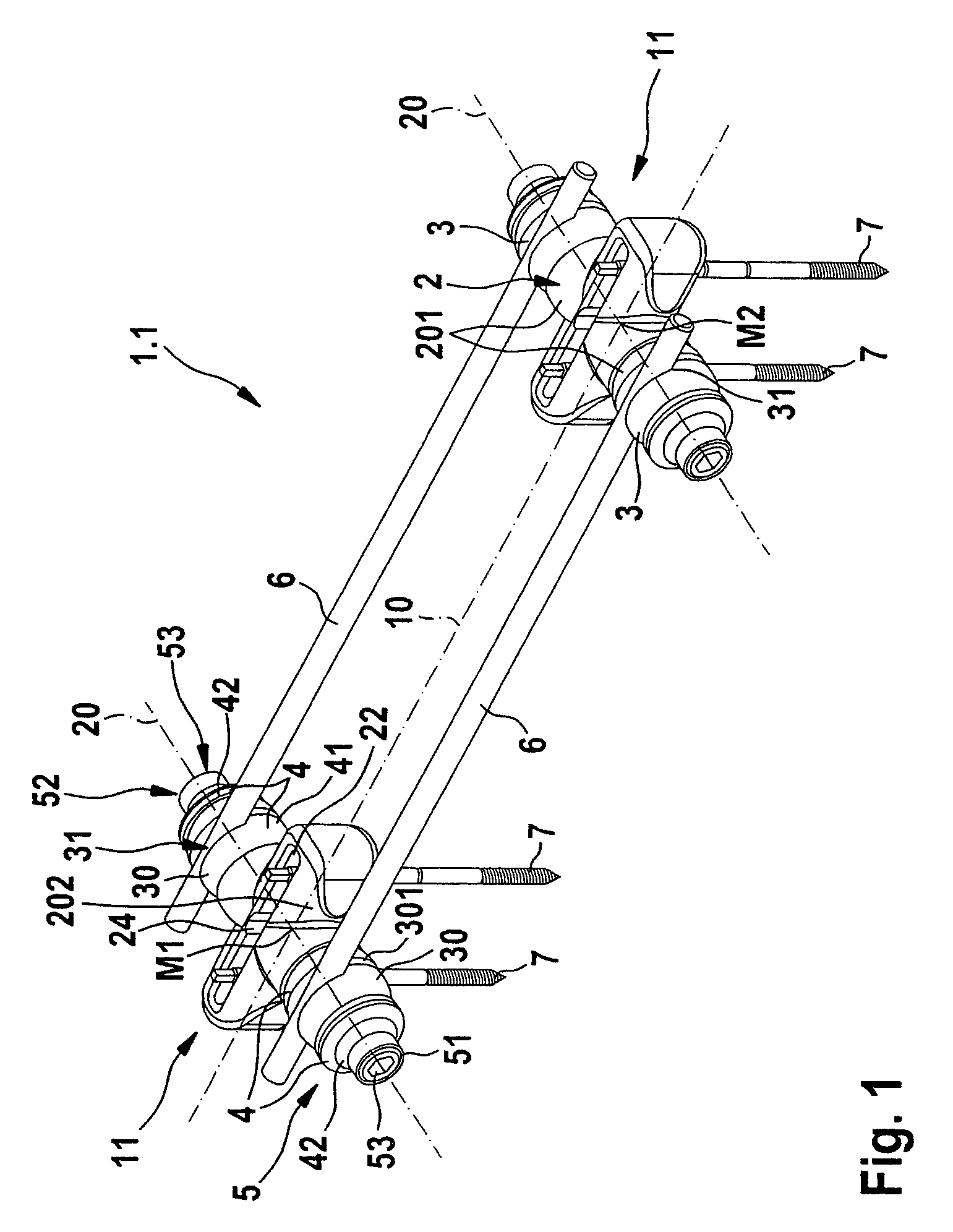
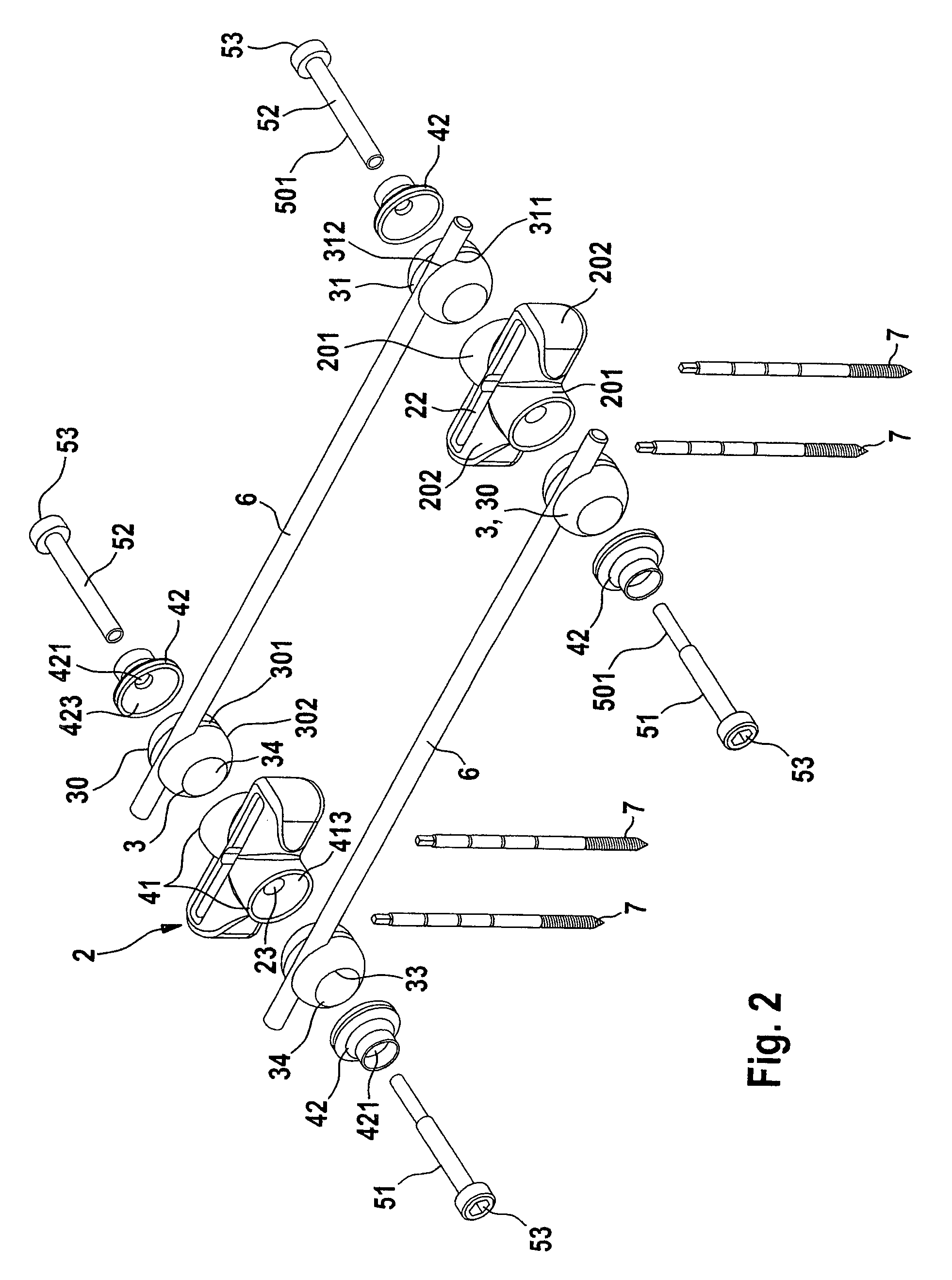
[0022]A first embodiment of a fixation device 1 according to the invention can be seen from FIGS. 1 and 2. This is composed of two fixation elements 11 according to the invention, bone nails 7 to which the elements 11 are applied, and two fixation rods 6. This is a fixator which with the two fixation rods 6 bridges a bone joint, e.g. a wrist, on the outside in order to make a fixation connection between broken bone portions. The fixation elements 11 are designed to match each other. The fixation rods 6 are shown in parallel alignment in FIGS. 1 and 2. But the device according to the invention allows them to be adjusted with a large deviation from parallel alignment as well. The bone nails 7 for the fixation element 11 each stand in a line which runs at least almost parallel to the fixation rods 6.

[0023]The fixation element 11 comprises a cross-shaped base body 2 which is made in one piece by a plastic part formed by injection moulding and to a certain extent is inherently deformable...


PUM


Abstract

A device to establish a connection of portions of a broken bone includes a base body adapted to receive a bone nail. A clamping holder has a receptacle to receive a fixation rod. A bearing element mounts the clamping holder on the base body for spherically displacement. A tensioning rod connection has a tensioning rod on which the base body, the clamping holder and the bearing element are arrangeable in a row for tensioning relative to each other. In a first connection state the tensioning rod connection is released so that the fixation rod and base body are adjustable relative to each other. In a second connection state there is sufficient closing tension in the tensioning rod connection to form a stable non-positive locking connection between the fixation rod and the base body. The clamping holder and the bearing element are in positive engagement in the first connection state with the tensioning rod passing through a through-opening of the clamping holder with sufficient play for spatial guiding in all directions.

Description

CROSS REFERENCE TO RELATED APPLICATION[0001]The present application is a U.S. National Stage of International Application No. PCT / EP2006 / 002951, filed Jan. 19, 2007, designating the United States and claiming priority to German application DE 20 2005 005 444.5, filed Apr. 1, 2005.BACKGROUND[0002]The invention concerns a fixation device for the stable connection of at least two bone portions of a broken bone, including at least one base body for tightly receiving at least one bone nail, at least one fixation rod which can be connected to the base body by means of a clamping joint, base body and fixation rod being released in a first connection state of the fixation device for adjusting their relative position and rigidly connected to each other by non-positive locking in a second connection state for fixing the adjusted position, a clamping holder which is mounted with adjustable angle on the base body and which receives a fixation rod for altering and adjusting its position in a rec...

Claims


Application Information

Patent Timeline
Patent Type & Authority Patents(United States)
IPC IPC(8): A61B17/00A61B17/64
CPCA61B17/645A61B17/6466
Inventor BAUER, ECKHARD
Owner TANTUM AG
Why Eureka
Eureka Blog
Learn More