Phase change memory featuring ferromagnetic layers in contact with phase change layer

a phase change memory and ferromagnetic layer technology, applied in the field of phase change memory, can solve the problems of difficult to distinguish the amorphous phase from the regular phase, and the regularity is deteriorated, and achieve the effects of high reliability, stable amorphous condition, and high tolerance against repeated rewriting

Inactive Publication Date: 2010-02-23
HITACHI LTD
View PDF3 Cites 9 Cited by
  • Summary
  • Abstract
  • Description
  • Claims
  • Application Information

AI Technical Summary

Benefits of technology

[0004]A first object, according to the present invention, is to provide a phase change memory, having high reliability. And, a second objection, according to the present invention, is to provide a phase change memory, being stable in the amorphous condition thereof. Also, a third objection, according to the present invention, is to provide a phase change memory, having high tolerance against the repetition of rewritings. Further, according to the present invention, a fourth object is to provide a phase change memory, being fast in the speed of rewriting.
[0006]Also, the inventors makes the fact clear that, when trying to improve the tolerance against repetition with applying a composition having high density of the lattice defects, while utilizing the knowledge of the Non-Patent Document 1 mentioned above therein, but the regularity is deteriorated in the atomic arrangement under the crystal condition (i.e., deleting condition), as an adverse reaction due to the fact that the lattice defects are much therein; therefore it is difficult to distinguish it from the amorphous phase. Then, the inventors found out that it is effective of letting the recording film or layer to have tensile or stretching strain therein, as a result of the zealous studies for obtaining a means to improve the tolerance against repetition, but without applying such the composition having high density of lattice defects. Further, they found that it is possible to obtain an effect of increasing the rewriting speed, by letting the recording film or layer the tensile or stretching strain therein.
[0008]And, according to the present invention, it is possible to provide a phase change memory, having high reliability. Also, according to the present invention, it is possible to provide a phase change memory, being stable in the amorphous condition thereof. Also, according to the present invention, it is possible to provide a phase change memory, having high tolerance against the repetition of rewritings. Further, according to the present invention, it is possible to provide a phase change memory, being fast in the speed of rewriting.

Problems solved by technology

Also, the inventors makes the fact clear that, when trying to improve the tolerance against repetition with applying a composition having high density of the lattice defects, while utilizing the knowledge of the Non-Patent Document 1 mentioned above therein, but the regularity is deteriorated in the atomic arrangement under the crystal condition (i.e., deleting condition), as an adverse reaction due to the fact that the lattice defects are much therein; therefore it is difficult to distinguish it from the amorphous phase.

Method used


Image

  • Phase change memory featuring ferromagnetic layers in contact with phase change layer
  • Phase change memory featuring ferromagnetic layers in contact with phase change layer
  • Phase change memory featuring ferromagnetic layers in contact with phase change layer

Examples


embodiment 1

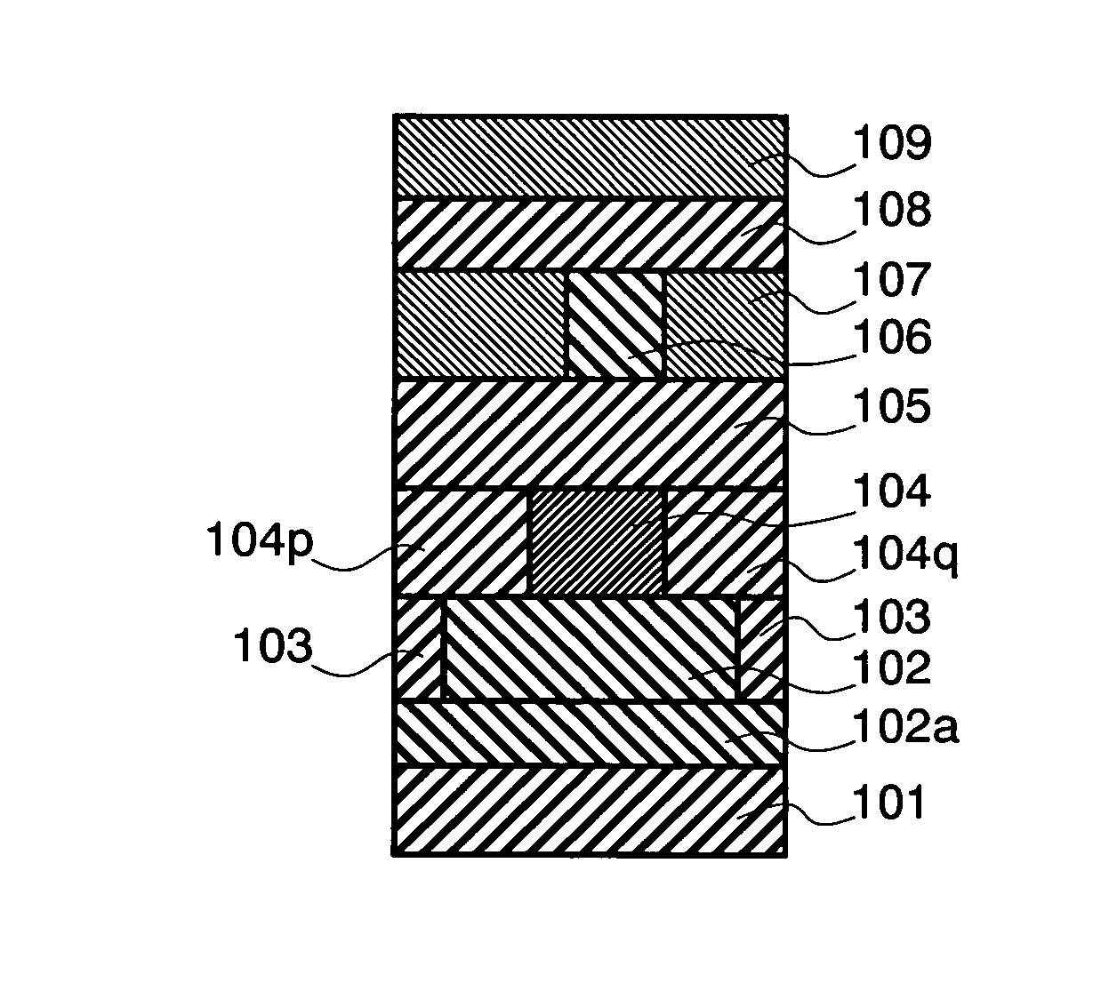
[0027]Next, the cross-sectional structure of a principle portion is shown in FIG. 1, first of all, in particular, within the phase change memory, according to the first embodiment of the present invention. Upon a silicon substrate 101 are built up layers, i.e., forming a wiring film or layer 102a, a lower electrode layer 102, an insulation layer 103, a phase-change recording layer 104, a ferromagnetic layer 104p, a ferromagnetic layer 104q, an upper electrode layer 105, a wiring layer 106, an insulating layer 107, a wiring layer 108, and an insulating layer 109, in that sequence thereof. Those are formed with applying the method, such as, the spattering, the chemical vapor deposition (CVD), or the plating, for example. The phase-change recording layer 104 includes at least two (2) elements therein, as the constituent ones thereof, which are selected from Ge, Sb and Te, and it is mainly composed from GeSb2Te4, Ge2Sb2Te5, Ge6Sb2Te9, or ZnSbxTey, ZnGexTey, ZnGeSbyTez, GeSbxTey, for exa...

embodiment 2

[0038]Next, in FIG. 10 is shown the cross-sectional structure of a principle portion within the phase change memory, according to a second embodiment of the present invention. The difference thereof from the first embodiment lies in that the lower electrode 102 is built up with two (2) layers 102b and 102c in the structure thereof, in the second embodiment. In this case, for a first lower electrode 102b, it is preferable to select a material having good adherence with the wiring layer 102a, and for a second lower electrode 102c, it is preferable to apply an amorphous material, having the atomic arrangement similar to that in the amorphous phase of the phase-change recording layer 104, in particular, for the purpose of stabilizing the amorphous phase of the recording layer 104. Such amorphous materials, having the atomic arrangement similar to that of the amorphous phase of the recording layer 104, as well as, being preferable to be the material of the second lower electrode 102c, ar...

embodiment 3

[0039]Next, in FIG. 11 is shown the cross-sectional structure of a principle portion within the phase change memory, according to a third embodiment of the present invention. The difference thereof from the first embodiment lies in that the insulation layer 103 is built up with two (2) layers 103a and 103b in the structure thereof, in the third embodiment. In this case, for a first insulation layer 103a, it is preferable to select a material having good adherence with the wiring layer 102a, and for a second insulation layer 103b, it is preferable to apply an amorphous material, having the atomic arrangement similar to that in the amorphous phase of the phase-change recording layer 104, in particular, for the purpose of stabilizing the amorphous phases of the lower electrode 102 and the recording layer 104. Such amorphous materials, having the atomic arrangement similar to that of the amorphous phase of the recording layer 104, as well as, being preferable to be the material of the s...


PUM


Abstract

A phase change memory comprises a phase-change recording layer for recording information through changing between a crystal phase and an amorphous phase; and a means for applying a tensile strain onto the phase-change recording layer, thereby providing the memory having high reliability, as well as, high tolerance or durability against repetitive rewriting operation.

Description

BACKGROUND OF THE INVENTION[0001]The present invention relates to a phase change memory, enabling to record, delete, rewrite and reproduce information, with using the phase change.[0002]As is described in the following Non-Patent Document 1, in accordance with a phase change recording method, write-in is conducted for information, with using the fact that a material of the recoding film or layer thereof causes the phase change, i.e., between the crystal phase and the amorphous phase, while read-out is conducted through determination on made on whether it is the crystal phase or the amorphous phase. In case when using a recording film material, such as, chalcogenide (for example, a material group of GeSbxTey), which is mostly applied in this method, because of a low stability of the amorphous phase, it is sometimes crystallized with the passage of time. Such the drawback is more serious, in particular, under the environment or circumstance of high temperature. And, as is also describ...

Claims


Application Information

Patent Timeline
Patent Type & Authority Patents(United States)
IPC IPC(8): H01L41/04H01L41/06H01L45/00
CPCG11C13/0004H01L45/06H01L45/1233H01L45/126H01L45/144H01L45/12H01L45/1253H01L27/2409H01L27/2436G11C2013/0095H10B63/20H10B63/30H10N70/801H10N70/8413H10N70/841H10N70/231H10N70/8828H10N70/826
Inventor IWASAKI, TOMIO
Owner HITACHI LTD
Why Eureka
Try Eureka