Multi-through hole testing plate for high throughput screening

a testing plate and multi-through hole technology, applied in the field of testing equipment, can solve the problems of increased overall cost of testing procedure, difficult operation of special delivery systems, and difficult filling of wells in testing apparatuses, etc., and achieve the effect of simplifying testing procedure, easy identification, and simplifying the construction of testing apparatus

Inactive Publication Date: 2010-02-23
LIFE TECH CORP
View PDF264 Cites 32 Cited by
  • Summary
  • Abstract
  • Description
  • Claims
  • Application Information

AI Technical Summary

Benefits of technology

[0013]The method and apparatus for holding samples for analysis in accordance with the present invention provides a number of advantages. For example, the present invention simplifies testing procedures. The samples of solution to be analyzed can be loaded into the testing plate by simply dipping or flooding one of the surfaces of the testing plate into the solution. As a result, the present invention does not require the use of a separate delivery systems for loading solution into the wells on the testing plate.
[0015]The present invention also permits an operator to more easily identify a particular hole filled with a sample for further analysis. Instead of spacing the holes equidistantly over the testing plate, the present invention arranges the holes in groups of at least two columns and two rows of holes and arranges the groups in sets of at least two or more. The groups are spaced further apart then the holes within each group and the sets of groups are spaced further apart then the groups are spaced apart. As a result, an operator can more easily identify a particular hole based upon which set, group, row, and column the hole is located in on the testing plate.

Problems solved by technology

Although these testing apparatuses work there are some problems.
For example, the wells in these testing apparatuses are difficult to fill.
These special delivery systems are often expensive and difficult to operate.
As a result, the overall cost of the testing procedure is increased.
Another problem with these prior testing apparatuses is with their construction.
However, the rest of the testing plate needs to be constructed of a non-transparent material.
The construction of a testing apparatus with these characteristics is difficult and expensive.
Yet another problem with these prior testing apparatuses is with the operator locating a particular well in the testing apparatus.
As a result, locating a particular well within the large number of wells is difficult.

Method used


Image

  • Multi-through hole testing plate for high throughput screening
  • Multi-through hole testing plate for high throughput screening
  • Multi-through hole testing plate for high throughput screening

Examples


Embodiment Construction

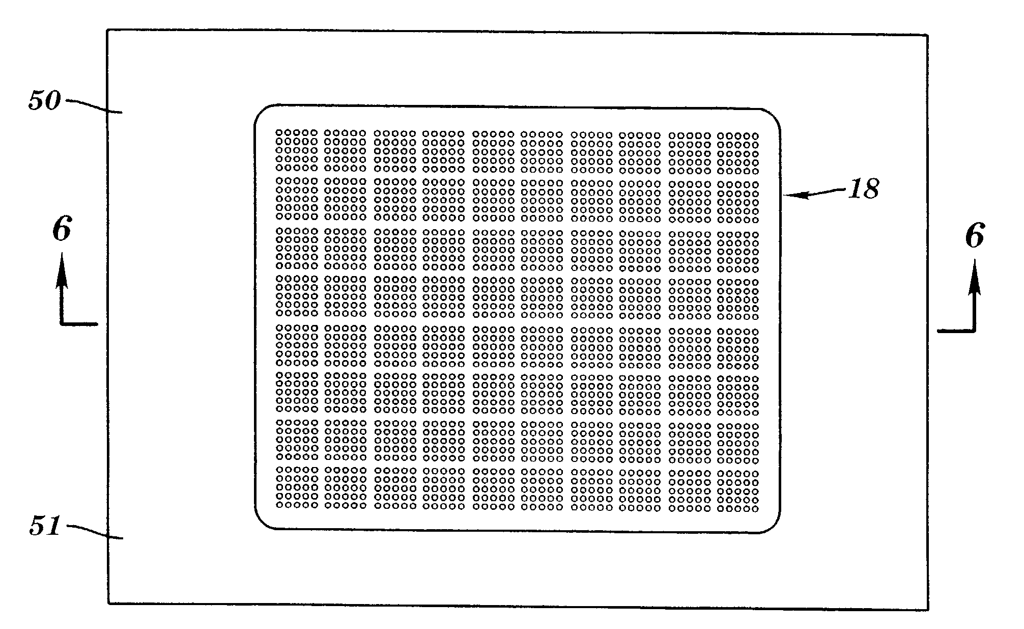
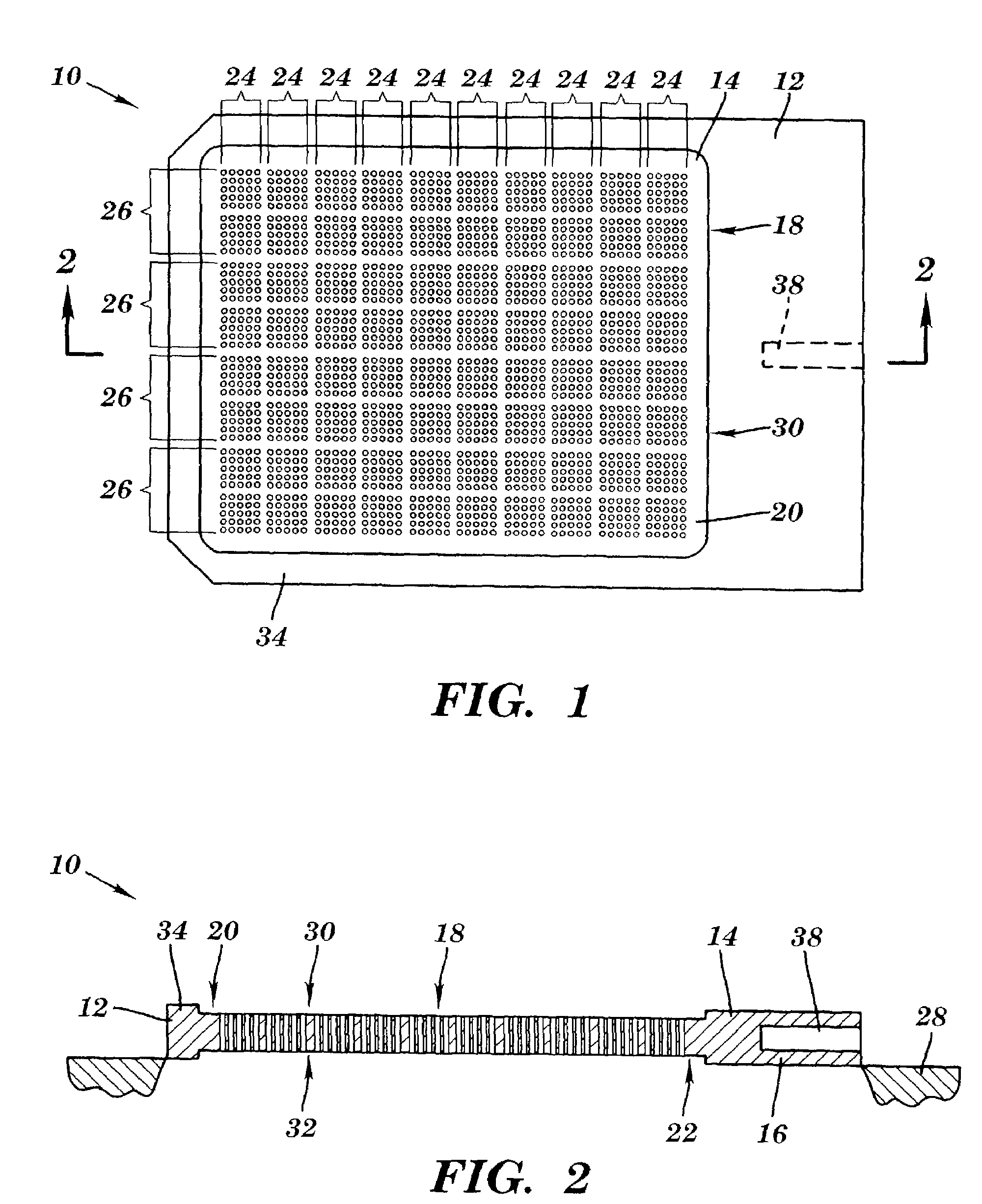
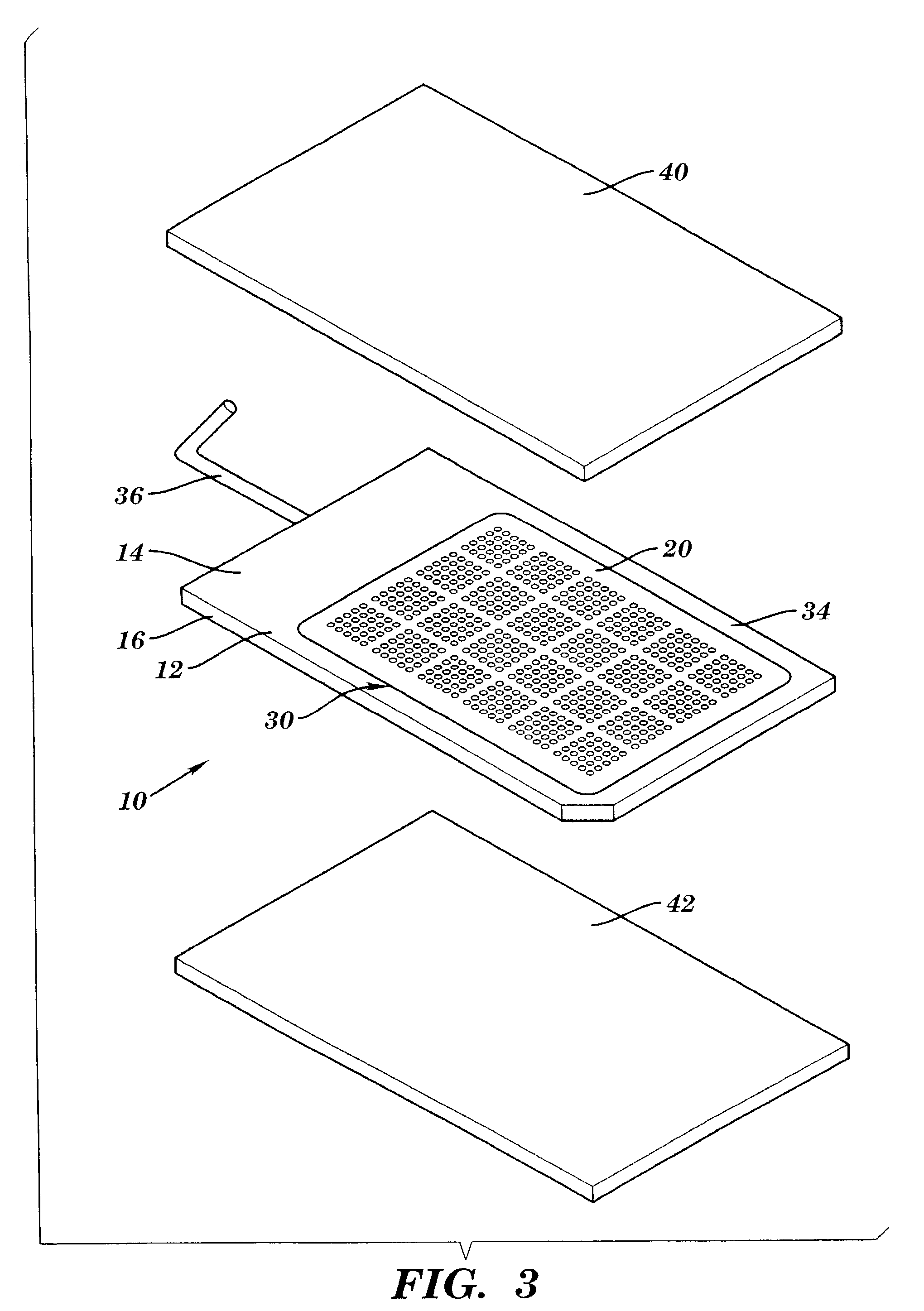
[0025]A testing apparatus 10 in accordance with one embodiment of the present invention is illustrated in FIG. 1. The testing apparatus 10 includes a testing plate 12 with a pair of opposing surfaces 14 and 16 (surface 16 is shown in FIG. 2) and a plurality of through holes 18. The through holes 18 are located in recessed portions 20 and 22 on each side of the testing plate 12. The through holes 18 are also arranged in groups 24 of at least two columns and two rows of holes 18 and in sets 26 of two or more groups of holes 18. The testing apparatus 10 provides a number of advantages including simplifying the procedure for loading samples of solution S into the holes 18 in the testing apparatus 10, simplifying the construction of the testing apparatus 10, and making the identification of a particular hole 18 filled easier for an operator.

[0026]Referring to FIGS. 1 and 2, the testing apparatus 10 includes the testing plate 12 which in this particular embodiment is made of a non-transpa...


PUM


Abstract

A method for holding samples for analysis and an apparatus thereof includes a testing plate with a pair of opposing surfaces and a plurality of holes. Each of the holes extends from one of the opposing surfaces to the other one of the opposing surfaces. The holes are arranged in groups, where each group has at least two rows and two columns of holes. The groups are arranged in sets, where each set has at least two rows and two columns of groups. To analyze samples, at least one of the opposing surfaces of the testing plate is immersed in a solution to be analyzed. A portion of the solution enters openings for each of the holes in the immersed opposing surface. Once the holes are filled with solution, the testing plate is removed and is held above a supporting surface. Surface tension holds the solution in each of the holes. The solution in one or more of the holes is then analyzed and the solution in one of these holes is identified for further study. The location of the identified solution is marked based upon its location within a particular set and group of holes.

Description

CROSS REFERENCE TO THE RELATED APPLICATIONS[0001]The present application is a continuation of prior U.S. patent application Ser. No. 09 / 970,578, filed Oct. 4, 2001, now U.S. Pat. No. 6,436,632 which in turn is a continuation of U.S. patent application Ser. No. 09 / 528,085, filed Mar. 17, 2000, now U.S. Pat. No. 6,306,578 which in turn is a continuation-in-part of prior U.S. patent application Ser. No. 09 / 471,852, filed Dec. 23, 1999, now abandoned which in turn is a continuation of U.S. patent application Ser. No. 09 / 272,122, filed Mar. 19, 1999, now U.S. Pat. No. 6,027,873 all of which are herein incorporated in their entireties by reference.FIELD OF INVENTION[0002]This invention is related generally to a testing apparatus and, more particularly, to a multi-through hole testing plate for high throughput screening.BACKGROUND OF THE INVENTION[0003]Prior testing apparatuses have consisted of a testing plate with a pair of opposing surfaces and a plurality of wells. The wells extend in ...

Claims


Application Information

Patent Timeline
Patent Type & Authority Patents(United States)
IPC IPC(8): B01L3/00B01J19/00C40B60/14G01N35/00G01N35/10
CPCB01J19/0046B01L3/5025B01L3/5085B01L3/50857B01J2219/00286B01J2219/00317B01J2219/00319B01J2219/0052B01J2219/00524B01J2219/00659B01J2219/00662B01J2219/00707C40B60/14G01N35/1065G01N2035/00237B01J2219/00533B01J2219/00596B01J2219/00644B01L2300/0654B01L2300/0809B01L2300/161
Inventor SCHELLENBERGER, VOLKERLIU, AMY DEMING
Owner LIFE TECH CORP
Why Eureka
Try Eureka