
Integrated image processor

a technology of image processor and image processing, applied in the field of integrated image processor, can solve the problems of large data volume, computational intensive processing of these images, and substantial latency in processing

Inactive Publication Date: 2010-02-16
INTEL CORP
View PDF9 Cites 63 Cited by
  • Summary
  • Abstract
  • Description
  • Claims
  • Application Information

AI Technical Summary

Benefits of technology

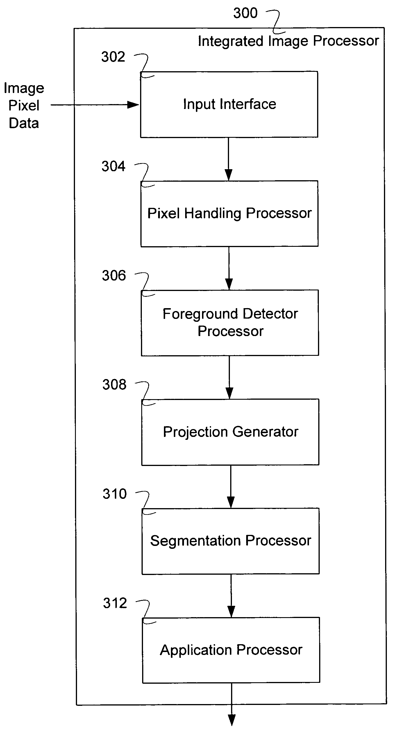
The invention is about a system and method for processing images to extract depth information from multiple cameras. The processing is performed by an integrated image processor that receives pixel data from the cameras and converts it into depth and intensity data. The system can also include a foreground detector, a projection generator, a segmentation processor, and an application processor. The technical effects of the invention include reducing latency and improving real-time image processing by reducing output arrays, reducing the amount of data that needs to be processed, and enabling real-time object detection and tracking. The invention can be implemented using techniques such as processors, apparatuses, systems, compositions of matter, computer storage media, and computer networks.

Problems solved by technology

The processing of these images is computationally intensive and requires the handling of large amounts of data.
Typically, the processing has substantial latency because it involves a series of calculations where one type of calculation is performed over an entire image before moving on to a next type calculation.

Method used


Image

  • Integrated image processor
  • Integrated image processor
  • Integrated image processor

Examples


Embodiment Construction

[0008]The invention can be implemented in numerous ways, including as a process, an apparatus, a system, a composition of matter, a computer readable medium such as a computer readable storage medium or a computer network wherein program instructions are sent over optical or electronic communication links. In this specification, these implementations, or any other form that the invention may take, may be referred to as techniques. A component such as a processor or a memory described as being configured to perform a task includes both a general component that is temporarily configured to perform the task at a given time or a specific component that is manufactured to perform the task. In general, the order of the steps of disclosed processes may be altered within the scope of the invention.

[0009]A detailed description of one or more embodiments of the invention is provided below along with accompanying figures that illustrate the principles of the invention. The invention is describ...


PUM


Abstract

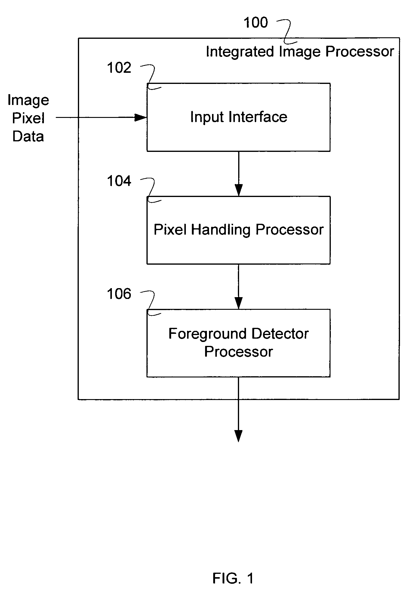
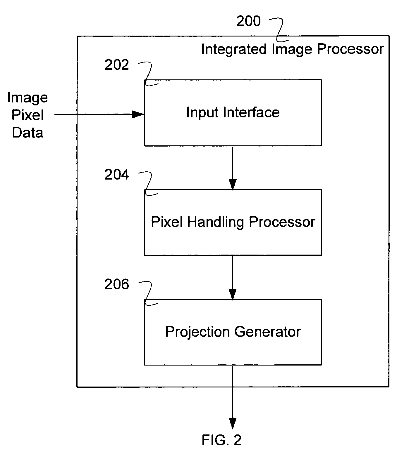
An integrated image processor implemented on a substrate is disclosed. An input interface is configured to receive pixel data from two or more images. A pixel handling processor disposed on the substrate is configured to convert the pixel data into depth and intensity pixel data. In some embodiments, a foreground detector processor disposed on the substrate is configured to classify pixels as background or not background. In some embodiments, a projection generator disposed on the substrate is configured to generate a projection in space of the depth and intensity pixel data.

Description

CROSS REFERENCE TO OTHER APPLICATIONS[0001]This application claims priority to U.S. Provisional Patent Application No. 60 / 624,954 entitled DEEPSEA G2 SYSTEM OVERVIEW filed Nov. 3, 2004 which is incorporated herein by reference for all purposes.BACKGROUND OF THE INVENTION[0002]Processing information of two (or more) images of the same scene, which originate from cameras slightly separated from one another, can yield depth information for objects in the images. The processing of these images is computationally intensive and requires the handling of large amounts of data. Typically, the processing has substantial latency because it involves a series of calculations where one type of calculation is performed over an entire image before moving on to a next type calculation. In addition, the output arrays from these calculations are usually large, sometimes including for each position in the image, depth information, intensity information, and color information. It would be useful to redu...

Claims


Application Information

Patent Timeline
Patent Type & Authority Patents(United States)
IPC IPC(8): G06K9/00G06K9/36
CPCG06K9/00791G06T7/0075G06K9/00986G06K9/00973G06T7/593G06V20/56G06V10/94G06V10/955
Inventor WOODFILL, JOHN ISELINBUCK, RONALD JOHNGORDON, GAILE GIBSONJURASEK, DAVID WALTERBROWN, TERRENCE LEE
Owner INTEL CORP
Learn More