
Steerable needle

a needle and steering technology, applied in the field of improved needles, can solve the problems of limited control available to the operator, limiting the success of minimally invasive surgery, missed target and need for a second insertion, etc., and achieve the effect of improving the guidance level of the operator

Inactive Publication Date: 2010-02-16
SALCUDEAN SEPTIMIU E +3
View PDF13 Cites 84 Cited by
  • Summary
  • Abstract
  • Description
  • Claims
  • Application Information

AI Technical Summary

Benefits of technology

"The present invention relates to a needle guidance system for medical applications. The system includes a needle with a steerable tip, an actuation system, a medical imaging device, a position sensor, and computing systems. The system can detect the needle in a medical image and provide the operator with a visual representation of the needle's location in real-time. The needle can be guided to a target using a mechanical guide or a robot. The system can also adjust the needle's direction of movement based on the operator's input. The technical effects of the invention include improved needle guidance, reduced risk of needle placement error, and improved operational efficiency."

Problems solved by technology

A significant factor limiting the success of minimally invasive, percutaneous procedures is the limited degree of control available to the operator over the path of the needle.
Choosing the correct insertion angle is itself challenging but compounding this difficulty is the tendency of fine needles (typically 20-22 gauge) to wander laterally from the insertion axis as the needle advances through the patient's tissue.
We have observed in the laboratory that these effects can noticeably bend the needle away from its apparent axis at the base resulting in a missed target and the need to perform a second insertion.
An additional limitation to the success of percutaneous needle procedures is the presence of bones, major blood vessels, nerves and other sensitive features in the body that may not leave a straight-line access to the target.
In such instances, minimally invasive needle procedures are generally not possible and the physician may then have to resort to surgery.
None of these patents provides the equipment or methodology to variably steer a medical needle during its insertion.
U.S. Pat. No. 5,345,937 describes a catheter steering system suitable for aiding in navigating branching blood vessels with a flexible catheter tube, but this system cannot steer fine, stiff needles through the body's flesh.
None of the existing systems provides motorized or computer-controlled actuation of the needle components nor do they provide visual feedback to aid in the physician's understanding and visualization of the needle and target positions inside the body.

Method used


Image

  • Steerable needle
  • Steerable needle
  • Steerable needle

Examples


Embodiment Construction

Basic Needle Structure

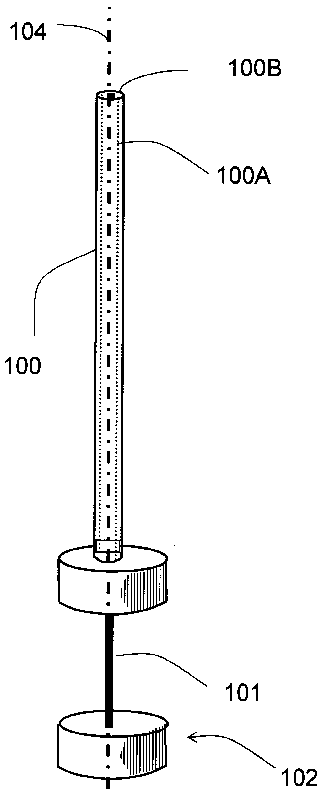
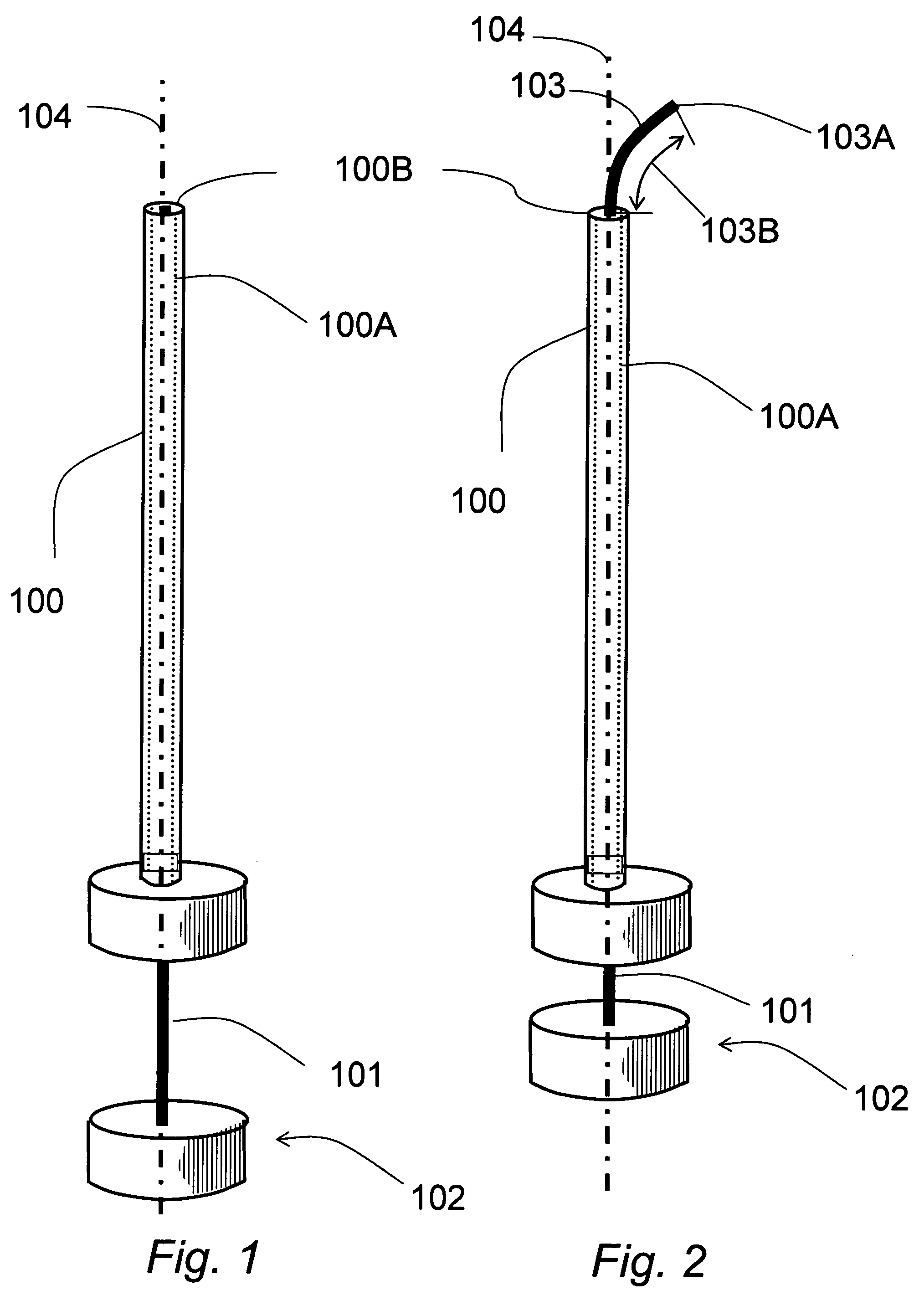
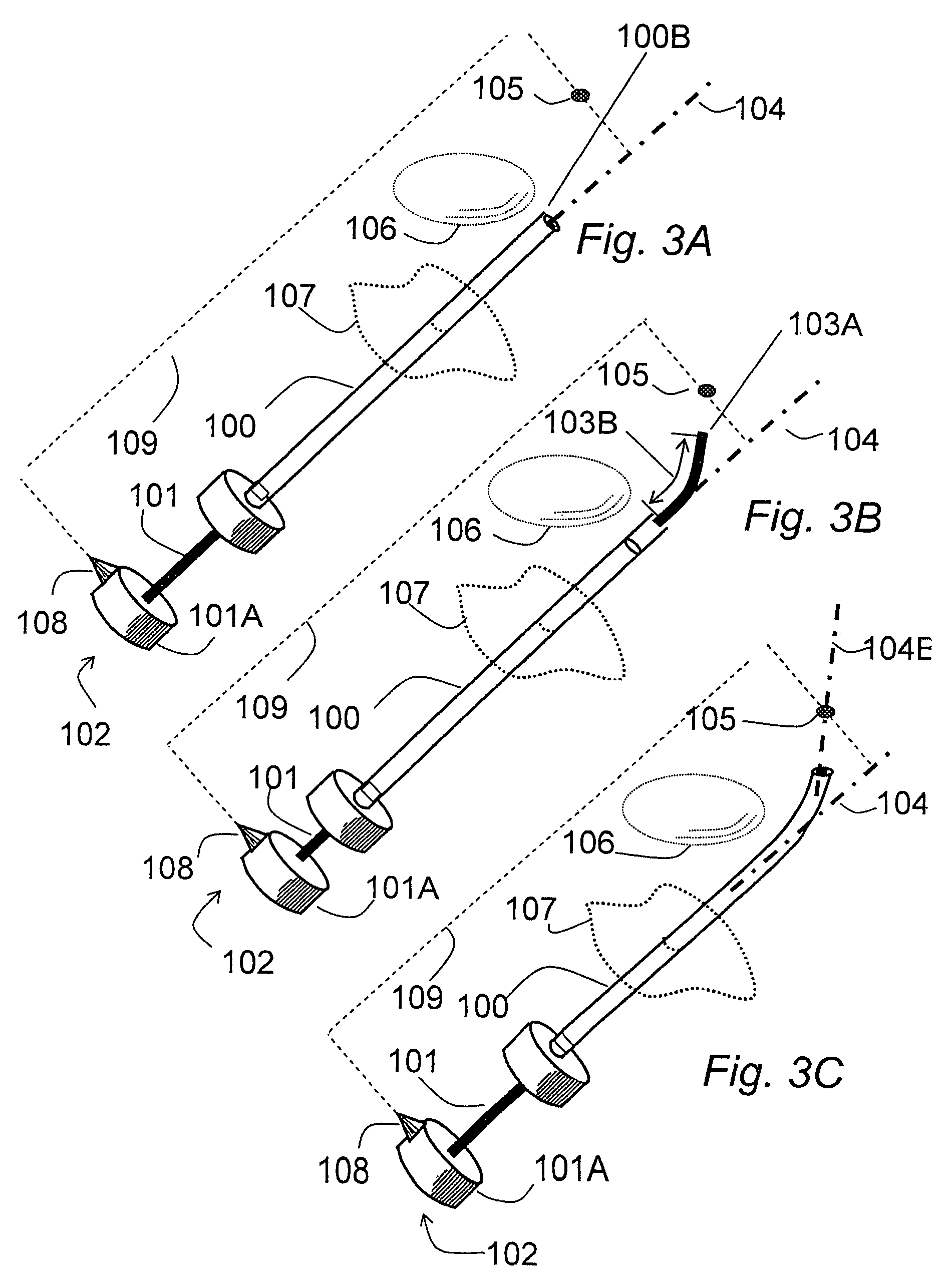
[0056]As shown in FIGS. 1 and 2, the needle 102 consists of two parts, namely, a cannula 100 having a hollow core 100A and a stylet 101 received within the hollow core 100A. The tubular or hollow cannula 100 in its natural unconstrained state is straight i.e. has a straight main or longitudinal axis 104. The stylet 101 is preferably a solid cylindrical element that may be inserted into the hollow core 100A of the cannula 100. The stylet 101 has a curved portion 103 adjacent to its free or leading end 103A that has a defined curvature in its natural unconstrained state. This curvature is preferably a smooth curve to allow the stylet to be easily extended into tissue and minimize tissue damage.

[0057]Typically, this curved end portion 103 of the stylet 101 extends from the free end or tip 103A up to about 2 centimeters (cm) and normally will have a curvature having a radius as small as 0.2 cm. Obviously the specific curvature and length of the curved portion 103 w...


PUM


Abstract

The invention relates to a needle guidance system provided by a needle with a steerable tip. The needle has a cannula and a stylet. The stylet adjacent to its tip has a naturally curved portion. The stylet is movable in two degrees of freedom with respect to the cannula—axial translation and axial rotation with respect to the cannula axis. When extended, the stylet curves off-axis and provides cannula tip steering. Driving and / or steering systems may be provided to the orientation and relatively move the stylet.

Description

FIELD OF THE INVENTION[0001]The invention relates to an improved needle that may be guided to a target.BACKGROUND TO THE PRESENT INVENTION[0002]Minimally invasive, percutaneous procedures have a wide variety of applications in medical diagnosis and therapy. Biopsy, delivery of localized therapy, and anesthesia are performed quickly and with minimal patient trauma using long, fine needles to access the desired site within the body via a puncture from the skin surface.[0003]A significant factor limiting the success of minimally invasive, percutaneous procedures is the limited degree of control available to the operator over the path of the needle. Once the needle tip has pierced the skin along the chosen axial trajectory, the operator has direct control only over insertion depth. Choosing the correct insertion angle is itself challenging but compounding this difficulty is the tendency of fine needles (typically 20-22 gauge) to wander laterally from the insertion axis as the needle adv...

Claims


Application Information

Patent Timeline
Patent Type & Authority Patents(United States)
IPC IPC(8): A61M31/00A61M25/00A61M5/00A61N1/30A61B10/00A61B10/04A61B17/00A61B17/34
CPCA61B10/04A61B17/3478A61B2010/045A61B2017/003A61B2017/00331A61B2017/00398A61B2017/00867A61B2017/3413
Inventor SALCUDEAN, SEPTIMIU E.ROHLING, ROBERT N.OKAZAWA, STEPHEN H.EBRAHIMI, AFROOZ R.
Owner SALCUDEAN SEPTIMIU E
Learn More