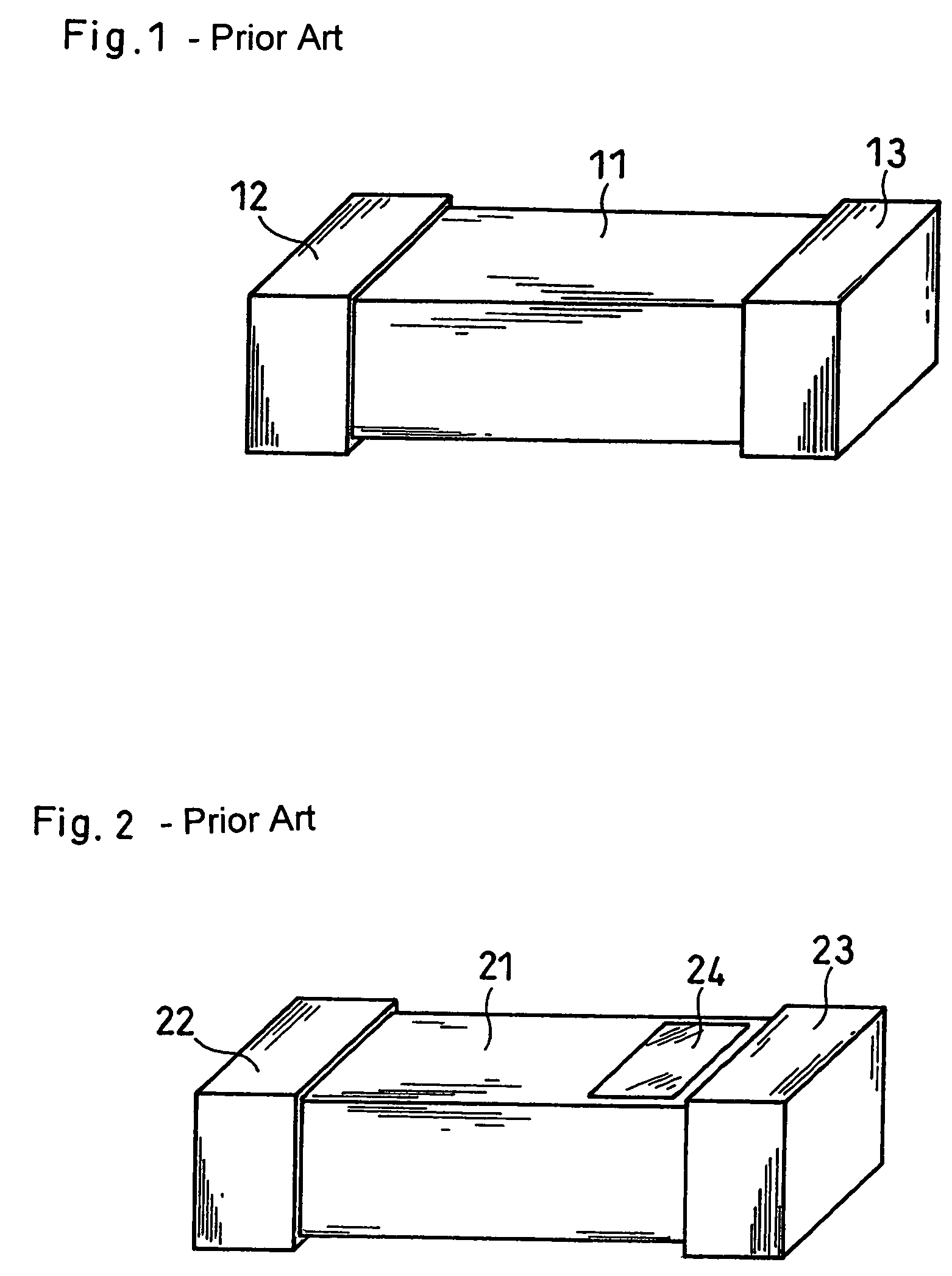
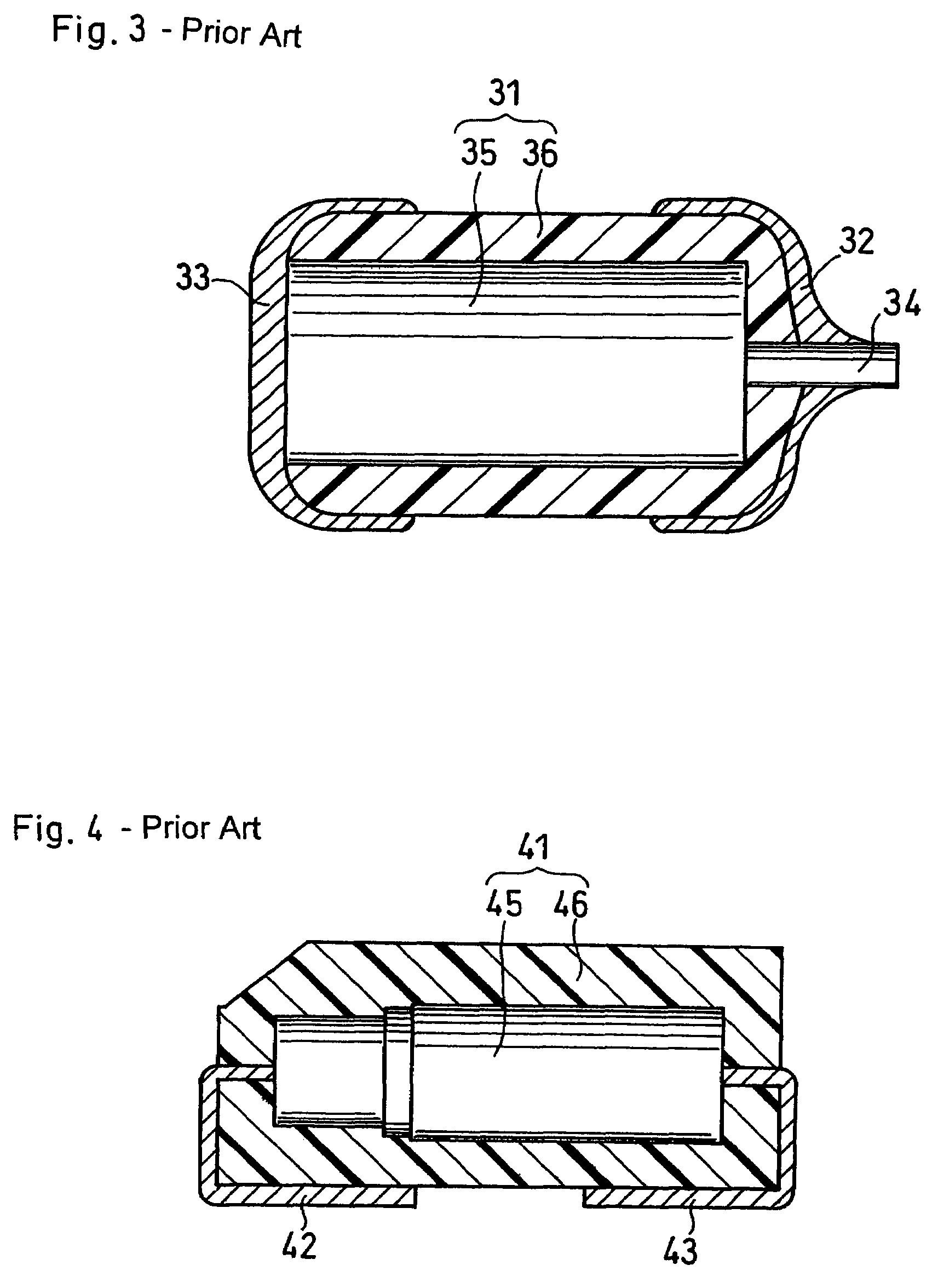
Chip-type battery
a chip-type battery and battery body technology, applied in the direction of sustainable manufacturing/processing, cell components, light absorption dielectrics, etc., can solve the problems of difficult to adopt the structure described above into electrochemical devices comprising a plurality of power generating elements which are stacked, and the mark is not applicable to electrochemical devices produced through sintering process, so as to achieve efficient reverse connection and low cost
- Summary
- Abstract
- Description
- Claims
- Application Information
AI Technical Summary
Benefits of technology
Problems solved by technology
Method used
Image
Examples
embodiment 1
[0035]Embodiment 1 will be described referring to FIG. 9. This embodiment relates to a chip-type battery comprising a body 91 having a substantially rectangular parallelepiped shape and containing a plurality of power generating elements which are stacked, a first terminal 92 having a first polarity and a second terminal 93 having a second polarity. Each power generating element comprises a sintered material. The first terminal 92 is provided at a first side face of the body 91. The second terminal 93 is provided at a second side face positioned opposite to the first side face. The battery as a whole is symmetric in shape with respect to the center of the body 91.
[0036]In this embodiment, the first terminal and the second terminal comprise different metal materials. Because different metal materials have different physical properties (e.g. absorbance wavelength, density, specific resistance, magnetism and the like) depending on the type of metal materials, the first terminal and the...
embodiment 2
[0042]A chip-type battery according to Embodiment 2 will be described with reference to FIG. 11. The chip-type battery shown in FIG. 11 comprises a body 101 having a substantially rectangular parallelepiped shape, a first terminal 102 having a first polarity and a second terminal 103 having a second polarity.
[0043]The first terminal 102 is provided at a first side face of the body 101. The second terminal 103 is provided at a second side face positioned opposite to the first side face. The body 101, the first terminal 102 and the second terminal 103 are combined such that the first terminal 102 and the second terminal 103 are symmetric with respect to the center of the body 101. In this embodiment, a button-shaped member 104 serving as an marking member is attached to the outer surface of the second terminal 103.
[0044]Although the marking member is button-shaped in FIG. 11, it may be in any shape as long as the marking member can be detected visually or by a machine. For example, as...
embodiment 3
[0049]A chip-type battery according to Embodiment 3 will be described with reference to FIG. 14. The chip-type battery shown in FIG. 14 comprises a body 141 having a substantially rectangular parallelepiped shape, a first terminal 142 having a first polarity and a second terminal 143 having a second polarity. This battery has the same structure as the battery of Embodiment 2 except that it has a marking member of different type.
[0050]In this embodiment, a magnetic material 144 serving as a marking member is attached to the body 141 in the proximity of a second terminal 143. More specifically, a paste containing a powdered magnetic material is applied to a certain portion of the body, followed by drying or sintering to attach the magnetic material to the body. The paste can be prepared by, for example, mixing a powdered magnetic material, a binder and a solvent. An example of the binder for use includes polyvinyl butyral. An example of the solvent includes butyl acetate.
[0051]When a ...
PUM
| Property | Measurement | Unit |
|---|---|---|
| shape | aaaaa | aaaaa |
| polarity | aaaaa | aaaaa |
| wavelengths | aaaaa | aaaaa |
Abstract
Description
Claims
Application Information
 - R&D
- Intellectual Property
- Life Sciences
- Materials
- Tech Scout
- Unparalleled Data Quality
- Higher Quality Content
- 60% Fewer Hallucinations
Browse by: Latest US Patents, China's latest patents, Technical Efficacy Thesaurus, Application Domain, Technology Topic, Popular Technical Reports.
© 2025 PatSnap. All rights reserved.Legal|Privacy policy|Modern Slavery Act Transparency Statement|Sitemap|About US| Contact US: help@patsnap.com


