
Screening module

a technology of material screen and screen, applied in the direction of sieving, solid separation, screening, etc., can solve the problems blockage or blinding of apertures, subjected to further processing, etc., and achieve the effect of facilitating the dislodging of material blinding apertures

Active Publication Date: 2010-02-02
F L SMIDTH & CO AS
View PDF13 Cites 32 Cited by
  • Summary
  • Abstract
  • Description
  • Claims
  • Application Information

AI Technical Summary

Benefits of technology

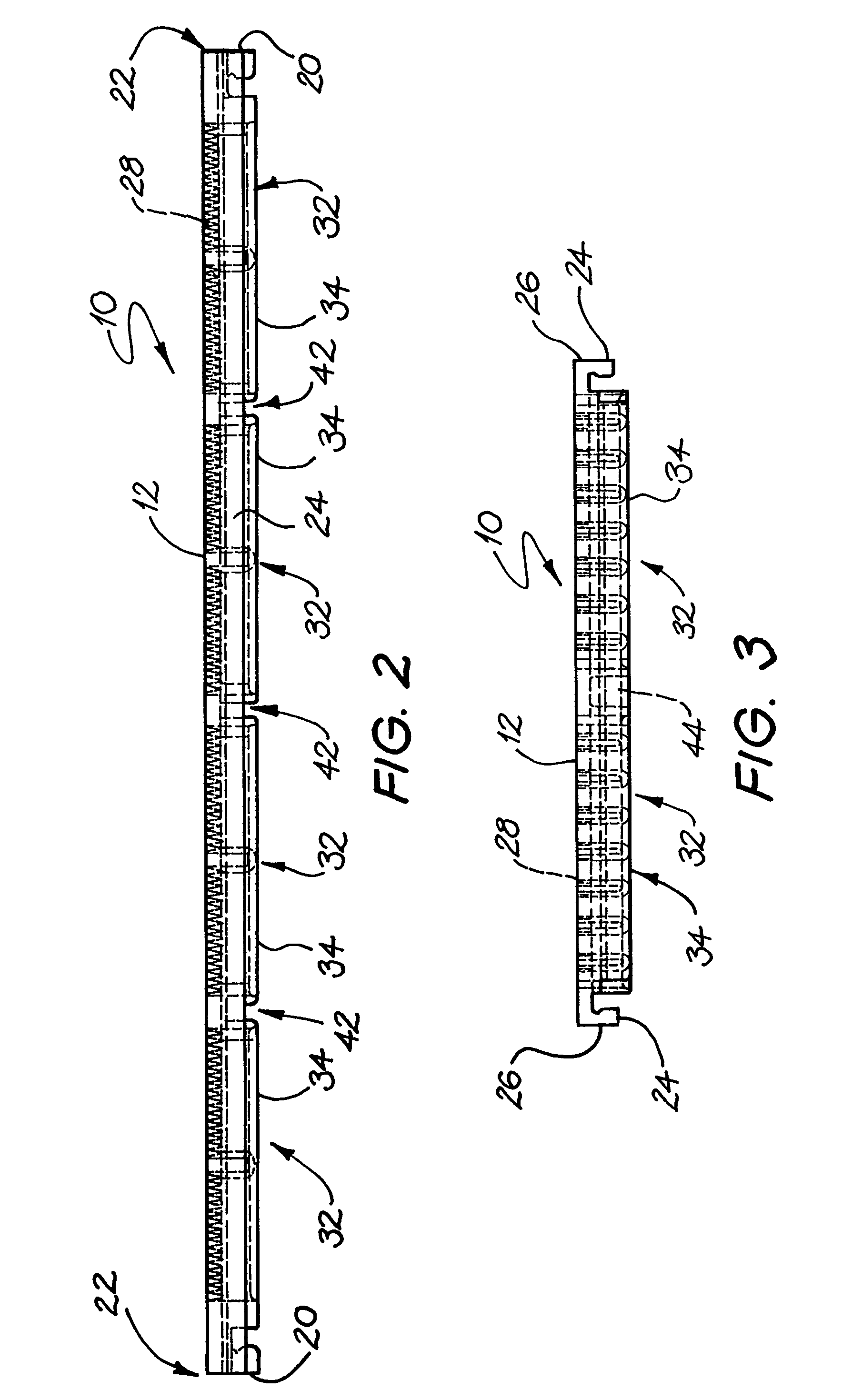
[0018]The skirt portions may be arranged such that channels are defined between adjacent parts of skirt portions of adjacent aperture arrays, the channels being dimensioned to be a sliding fit over support members of the underlying frame. Each channel may permit vertical displacement of the panel member relative to the underlying support members to permit a degree of damped, or controlled, sliding movement between the skirt portions and the support members to facilitate dislodging of material blinding apertures of the screening module by the panel member of the screening module impacting against the support members. It will therefore be appreciated that the skirt portions grip the support members without engaging them in a clipping or locking manner.

Problems solved by technology

However, with these fine apertures, there is a danger of the apertures becoming blocked or blinding so that, what may be undesirable material, traverses the screen deck and is also subjected to further processing.

Method used


Image

  • Screening module
  • Screening module
  • Screening module

Examples


Embodiment Construction

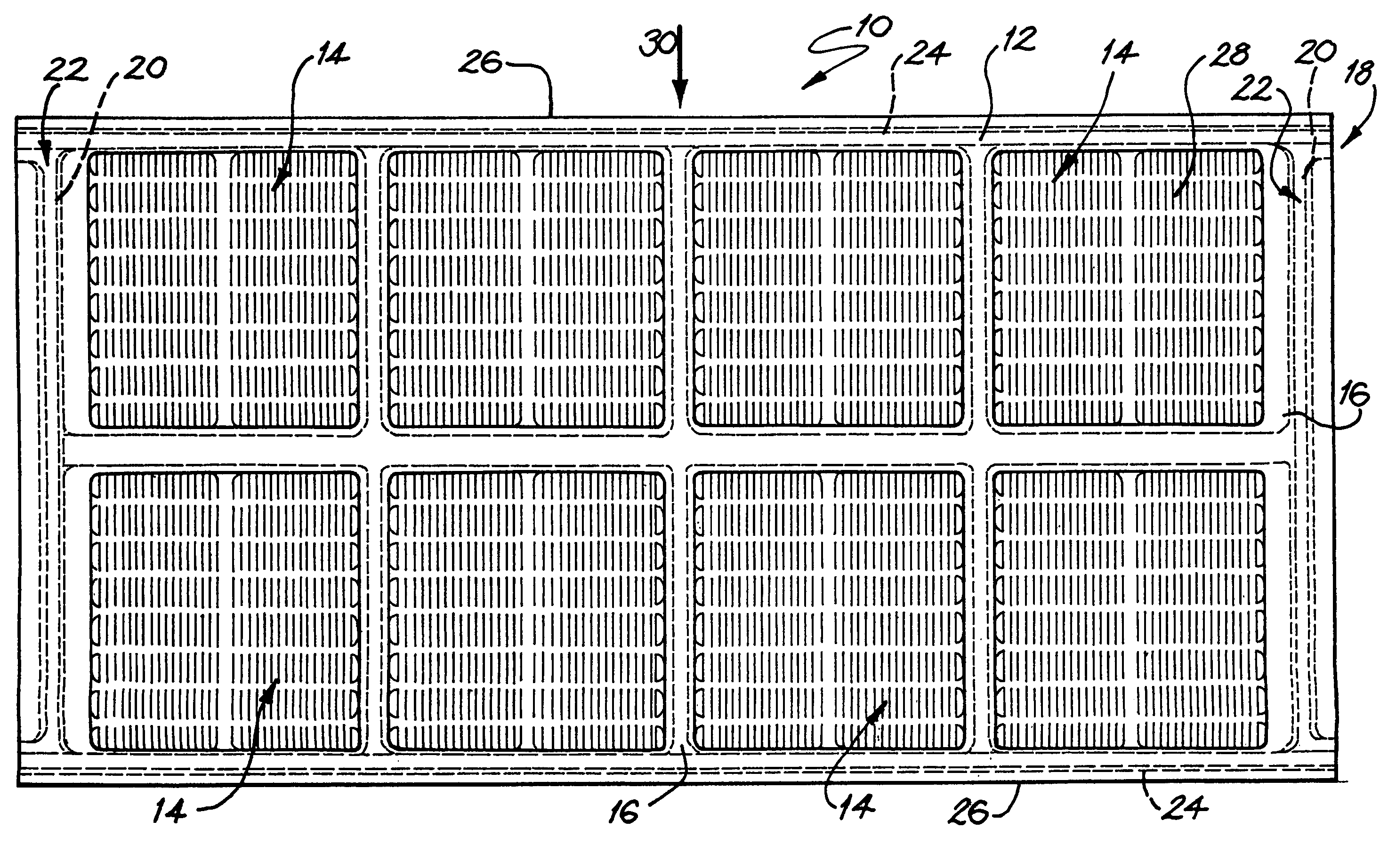
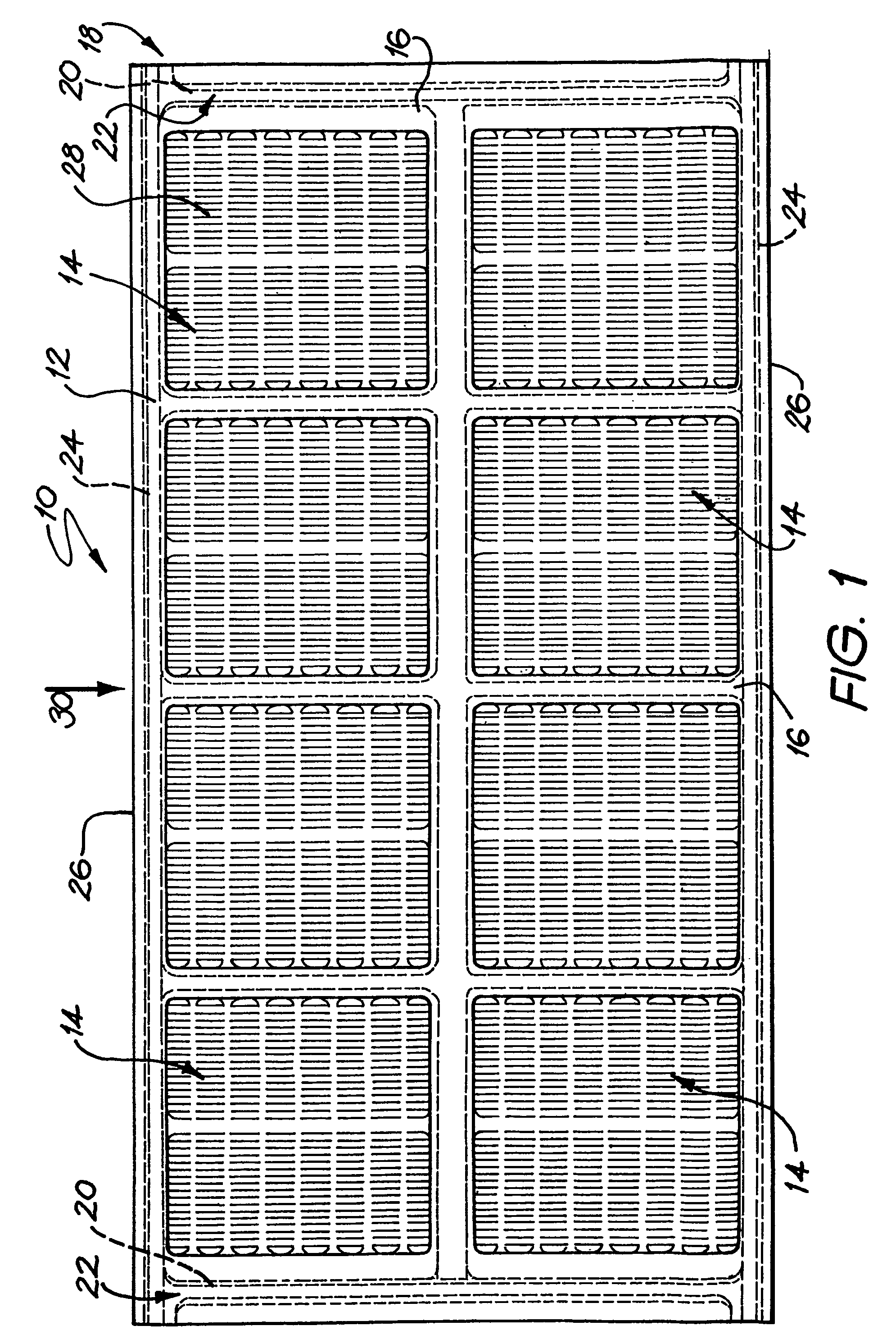
[0030]In the drawings, reference numeral 10 generally designates a screening module, in accordance with an embodiment of the invention.

[0031]The module 10 comprises a panel member 12 defining a plurality of discrete aperture arrays 14. It will be noted that a matrix of aperture arrays 14 is defined in the panel member 12. Each array 14 is separated from its neighbouring array / s by material 16 of the panel member 16.

[0032]The screening module 10 includes a mounting formation 18 in the form of a plurality of clips 20, 24 arranged about a periphery of the panel member 12. A clip 20 is provided at each end 22 of the panel member 12. In addition, a clip 24 is provided along each side 26 of the panel member 12. The panel member 12 is substantially rectangular in shape having shorter ends 22 and longer sides 24. In use, the ends 22 are arranged parallel to a direction of flow of material over the panel member 12 as generally indicated by the arrow 30. It is also to be noted that the apertu...


PUM


Abstract

A screening module for a screening assembly includes a panel member having a periphery defined by a pair of opposed, parallel sides and a pair of opposed parallel ends. A mounting formation is arranged about at least a part of the periphery of the panel member for mounting the panel member on an underlying frame. A plurality of discrete aperture arrays are defined in a surface of the body member. A skirt portion circumscribes each aperture array, each skirt portion depending from a lower surface of the panel member. A reinforcing arrangement is arranged beneath each aperture array, the reinforcing arrangement being bounded by its associated skirt portion.

Description

CROSS-REFERENCE TO RELATED APPLICATIONS[0001]The present application claims priority from Provisional Patent Application No. 2003906517 filed on 25 Nov. 2003, the contents of which are incorporated herein by reference.FIELD OF THE INVENTION[0002]This invention relates to the screening of materials. More particularly, the invention relates to a screening module for use in a screening assembly which screens material to classify or sort the material. The invention also relates to a screening assembly including the screening module.BACKGROUND TO THE INVENTION[0003]Screening arrangements are widely used in the mining industry, particularly the coal mining industry, for the screening or classifying of ores and slurries. Material to be screened is passed over a vibratory screen deck. Apertures of screening panels arranged on the screen deck pass material having dimensions smaller than the apertures of the screen panels while materials having dimensions larger than those of the screening ap...

Claims


Application Information

Patent Timeline
Patent Type & Authority Patents(United States)
IPC IPC(8): B07B1/49B07B1/46
CPCB07B1/4609B07B1/4645
Inventor JOHNSON, RONALD LESLIEMCGREGOR, RONALD KEITH
Owner F L SMIDTH & CO AS
Learn More