
Compact compound engine package

a compound engine and engine technology, applied in the direction of engine fuction, engine cooling apparatus, air transportation, etc., can solve the problems of failure to detail a complete solution and weak solution of prior art compound cycle engine designs

Active Publication Date: 2010-02-02
PRATT & WHITNEY CANADA CORP
View PDF30 Cites 34 Cited by
  • Summary
  • Abstract
  • Description
  • Claims
  • Application Information

AI Technical Summary

Benefits of technology

[0008]It is also an aim of the present invention to provide a compact self cooling system for a rotary combustion device.

Problems solved by technology

However, to date, proposed compound cycle engine designs have been bulky and therefore failed to detail a complete solution to the integration of a cycle topping device, such as a rotary combustion engine, with a gas turbine in a compact packaging suitable for aero applications, such as aviation.
Moreover, prior art compound cycle engine designs have been weak in providing solutions to the cooling of internal combustion engines which are practical and realistically viable in an aircraft environment.

Method used


Image

  • Compact compound engine package
  • Compact compound engine package
  • Compact compound engine package

Examples


Embodiment Construction

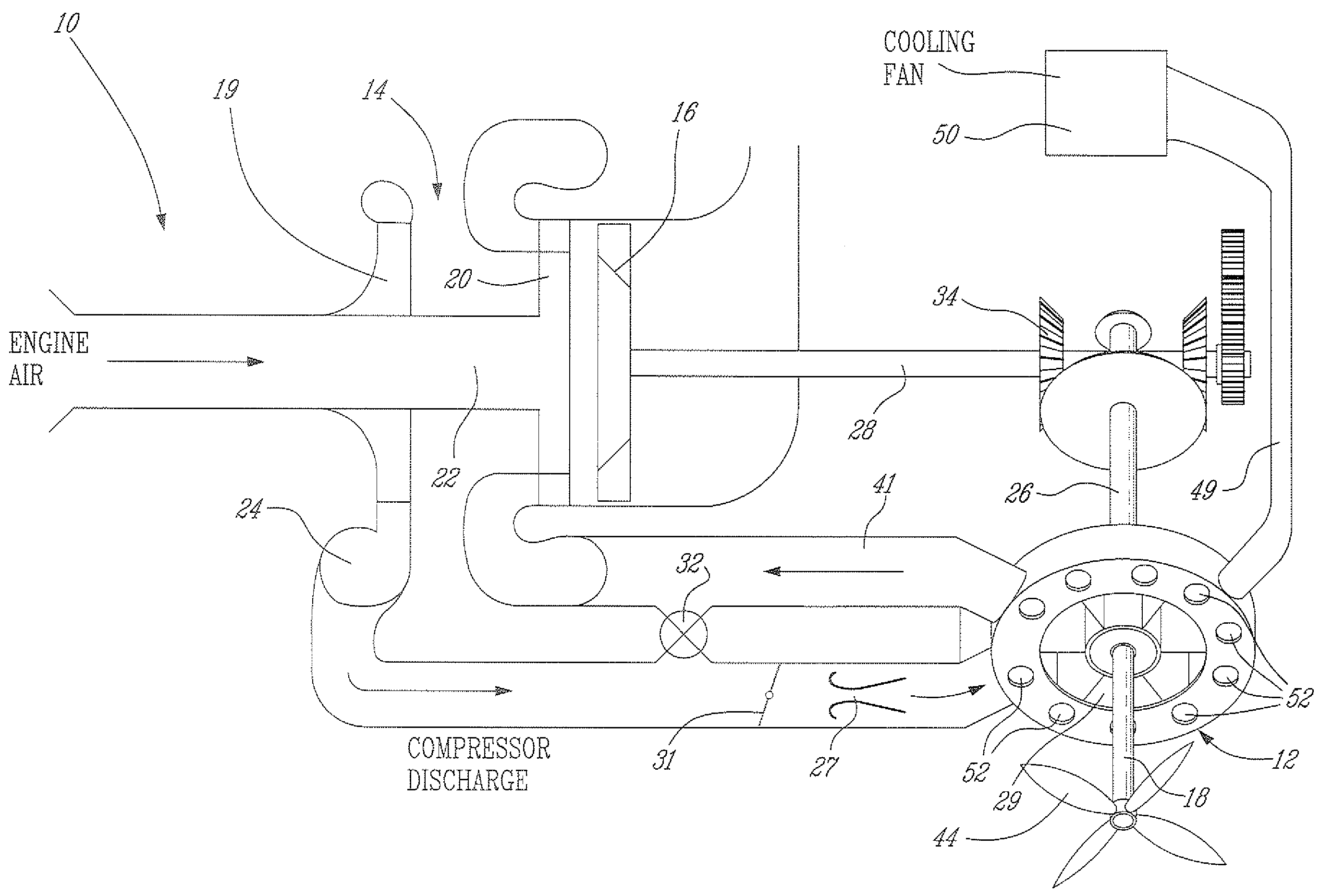
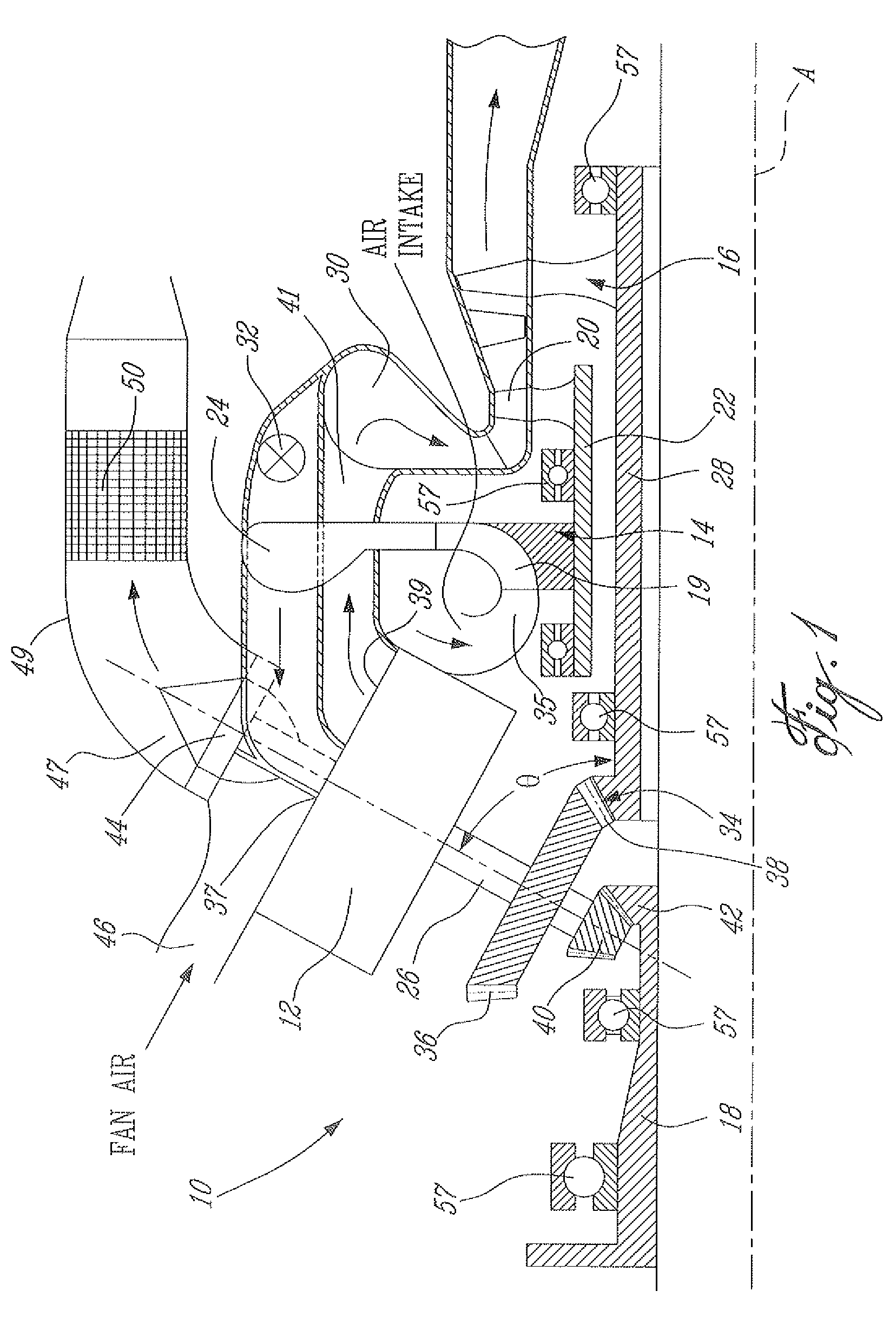
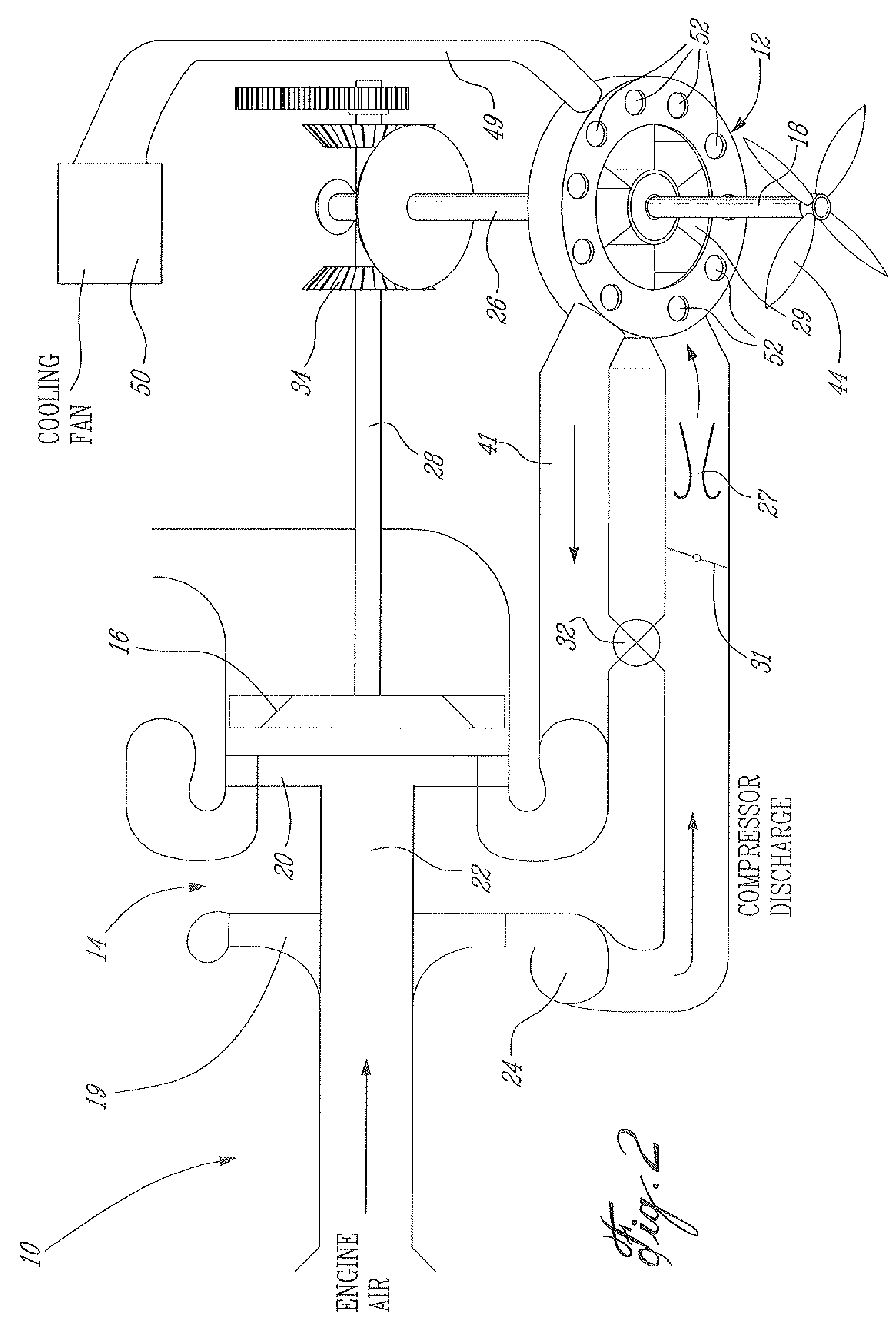
[0022]FIG. 1 is a schematic representation of a compound cycle engine 10 of a type preferably provided for use in a variety of aero applications, such as turboshaft, turboprop or APU (auxiliary power unit) applications. Referring to FIG. 1, it can be seen that the compound cycle engine 10 generally comprises at least one rotary cycle turbine topping device (TTD) 12 (preferably 1 or 2, as indicated in FIG. 1) and a gas turbine engine 14, which acts as a turbocharger. Turbocharger 14 comprises a compressor 19, a first stage turbine 20 and a second stage or power turbine 16. A hollow shaft 22 connects first stage turbine 20 to compressor 19. The power turbine 16 is preferably a free turbine and includes a power turbine shaft 28 concentrically disposed within the hollow shaft 22 for independent rotation with respect thereto about a main engine axis 4. The shaft 28 connects power turbine 16 to the rotary cycle topping device 12 via a bevel gearset 34. Preferably the bevel gear set 34 has...


PUM


Abstract

A compound cycle engine (10) comprises a compressor (19) and a turbine section (16&20), and at least one cycle topping device (12) cooperating with the turbine section (16&20) to provide power. The cycle topping device (12) has an output shaft (26) extending at an angle to the turbine shaft (28). Angled gearing (34) is provided for connecting the gas turbine shaft (28) and the cycle topping device (12).

Description

RELATED APPLICATIONS(S)[0001]This application is a continuation of International Patent Application No. PCT / CA2004 / 000259 filed on Feb. 24, 2004, which claims benefit of Canadian Patent Application Nos. 2,419,692 and 2,419,691 filed on Feb. 24, 2003, all of which are herein incorporated by reference.BACKGROUND OF THE INVENTION[0002]1. Field of the Invention[0003]The present invention relates to compound cycle engines and, more particularly, to a compact compound engine package suitable for aircraft applications.[0004]2. Description of the Prior Art[0005]There have been attempts to developed compound cycle engines having internal combustion engines and turbine engines, coupled together to provide a common output. For example, see U.S. Pat. No. 4,815,282. However, to date, proposed compound cycle engine designs have been bulky and therefore failed to detail a complete solution to the integration of a cycle topping device, such as a rotary combustion engine, with a gas turbine in a com...

Claims


Application Information

Patent Timeline
Patent Type & Authority Patents(United States)
IPC IPC(8): F02G3/00F02B33/44F16H37/06F01D25/12F01D25/26F02C5/06F02C7/12F02C7/18F02K99/00
CPCF01D25/12F01D25/26F02C5/06F02C7/12F02C7/18Y10T74/1906Y02T50/671Y02T50/676F05D2260/20F05D2250/314Y02T10/12Y02T50/60
Inventor ULLYOTT, RICHARD
Owner PRATT & WHITNEY CANADA CORP
Learn More