
Method and device for processing an incident signal, in particular for filtering and analog/digital conversion

a technology of incident signals and filtering, applied in the direction of code conversion, pulse techniques, instruments, etc., can solve the problems of not being able to follow the same evolution of external elements of the analog part of the signal processing, and not being able to fabricate analog and digital parts, so as to achieve the effect of easy calculation

Inactive Publication Date: 2010-01-26
ST ERICSSON SA
View PDF5 Cites 1 Cited by
  • Summary
  • Abstract
  • Description
  • Claims
  • Application Information

AI Technical Summary

Benefits of technology

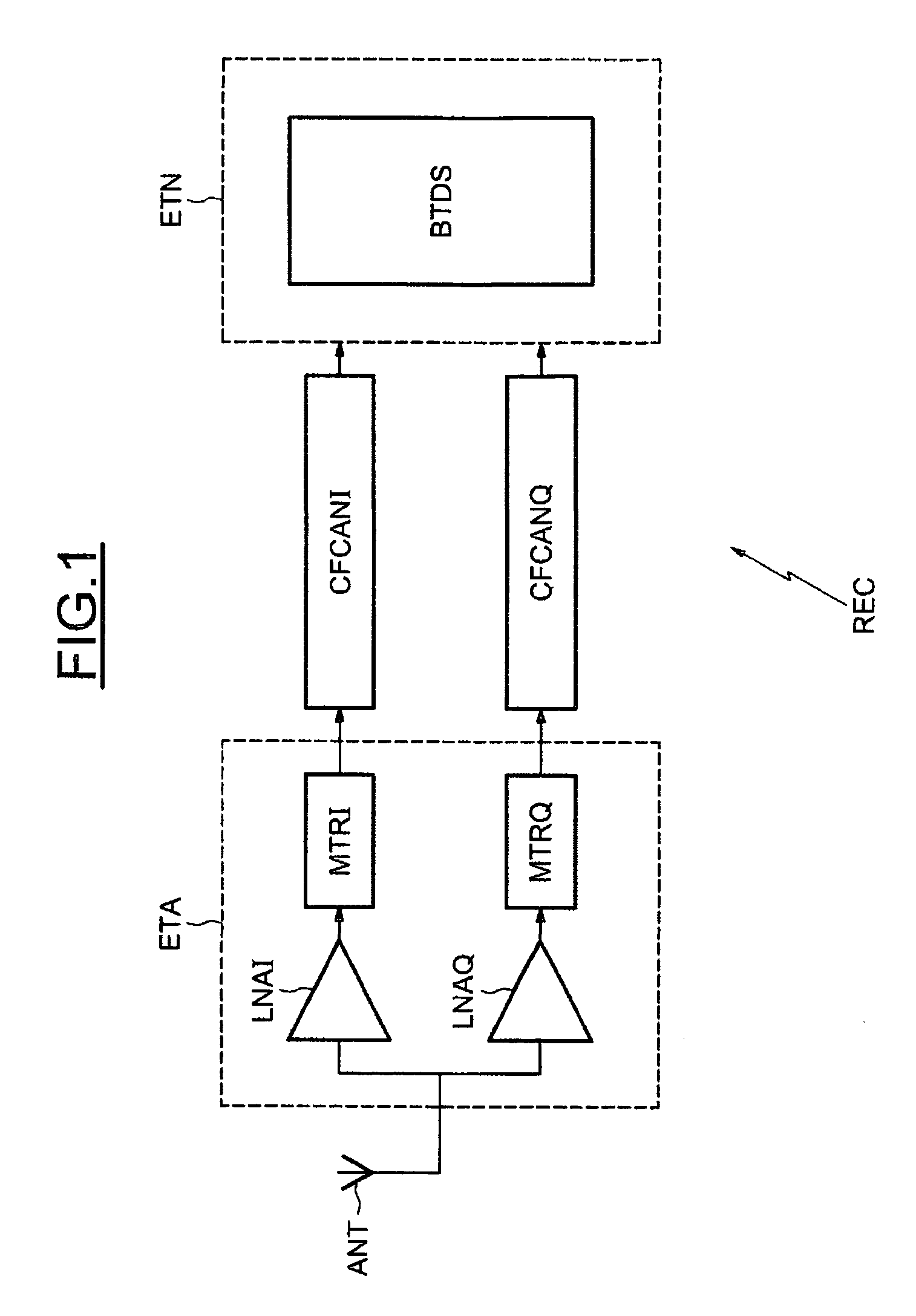
[0012]This solution offers the advantage of mixing within the same circuit the filtering and analog / digital conversion stages, which allows the design cost and the processing chain noise to be reduced. A further advantage is the use of the technique of passive switched capacitances, for both the filtering and for the analog / digital conversion which, in particular, allows a high sampling frequency to be adopted.
[0078]This embodiment can be applied whether the working frequency of the filter is equal to or different from the control frequency FS. This embodiment allows the reformatting step and the final digital filtering step to be carried out at the same time. This avoids the need for a digital signal with a large number of bits between the reformatting filter and the final digital filtering, owing to the reformatting of the signal even outside of the desired frequency range. For this purpose, it suffices to multiply the two transfer functions together so as to obtain only one from them. The signal obtained at the output of the filter remains the same but this results in the fabrication of the device being simplified.

Problems solved by technology

It is not therefore possible to fabricate the analog part and the digital part of a radio frequency signal processing device on a single integrated circuit.
Moreover, the external elements of the analog part of the signal processing are not able to follow the same evolution, notably in terms of size, as the digital part fabricated using CMOS technology.

Method used


Image

  • Method and device for processing an incident signal, in particular for filtering and analog/digital conversion
  • Method and device for processing an incident signal, in particular for filtering and analog/digital conversion
  • Method and device for processing an incident signal, in particular for filtering and analog/digital conversion

Examples


first embodiment

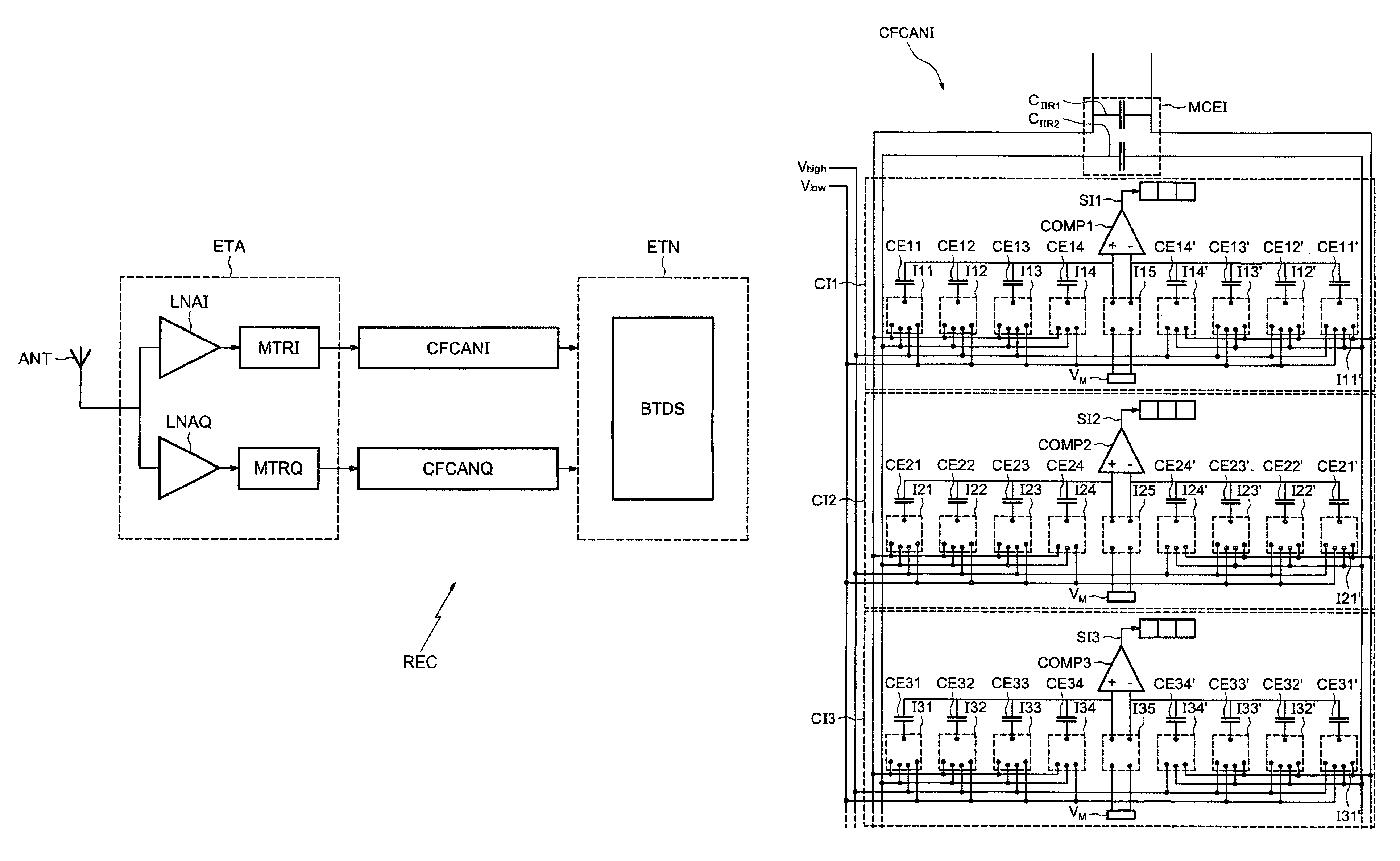
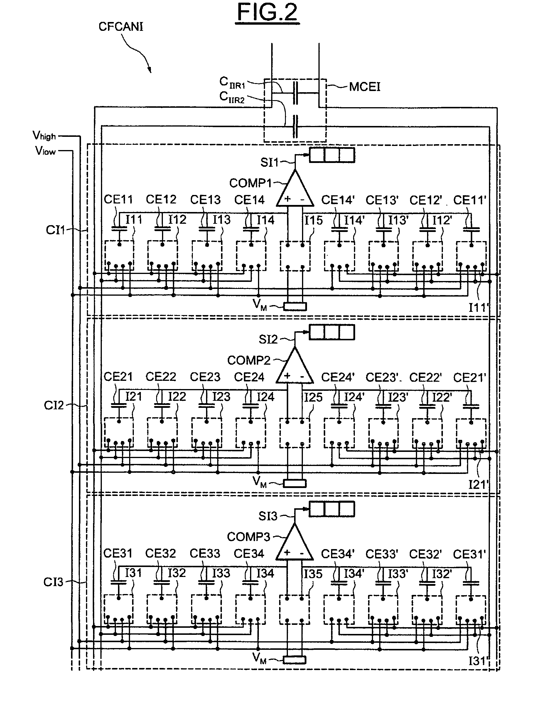
[0158]FIG. 2 shows the filtering and analog / digital conversion circuit CFCANI, using differential architecture. It goes without saying that this embodiment is not limited to a differential architecture, and those skilled in the art will readily be able to adapt the description that follows to a non-differential architecture.

[0159]In this embodiment, the circuit CFCANI comprises input capacitance means MCEI comprising two filtering capacitors CIIR1 and CIIR2. The filtering capacitors CIIR1 and CIIR2 are capacitors referred to as ‘memory capacitors’ whose capacitance is high and is not reset to zero. It also comprises elementary circuits allowing, on the one hand, the intermediate signal to be filtered with the input capacitance means MCEI and, on the other, the filtered intermediate signal to be converted by successive approximations in such a manner as to deliver samples with N bits of a digital output signal. In view of the number (2) of filtering capacitors and of the fact that th...

second embodiment

[0200]This is because by introducing a signal of known frequency and amplitude into the circuit CAFCANI′, it is possible to deduce therefrom the transfer function G1 of the low-pass filtering at the frequency of the signal. In particular, in the case of the second embodiment, it is possible to introduce such a signal only by modifying the switching states of the switches during the reference state, without introducing an intermediate signal at the current input. An example of a method of determining the transfer function G1 of the low-pass filtering at a given frequency is described below.

[0201]FIG. 12 shows the first configuration state of the circuit CAFCANI′ during the method of determining the transfer function G1 of the low-pass filtering at a given frequency. In this first state, the first elementary circuit CI1′ is placed in a reference state different from that of the conventional operation described previously. This is because all the switches of the first elementary circui...

third embodiment

[0283]In a third embodiment, the case is considered in which the filter FRFI is also run at a working frequency FS / Ndiv different from the sampling frequency FS of the analog / digital converter CANI, and the filter FPBAI is a low-pass filter of order 1 and of cutoff frequency f0. As previously, the transfer function of the reformatting filter FRFI is an approximation Happrox of the inverse H of the transfer function of the filter FPBAI. It will also be considered that the filter FRFI is of the finite-impulse-response type of order Nfir=2N−1. The transfer function Happrox of the filter FRFI can be written in the form:

[0284]Happrox=1+∑n=1n=N-1⁢αn⁡(zn-z-n)⁢⁢with⁢⁢z-n=ⅇ2⁢ⅈπ⁢⁢n⁢fNdiv⁢Fs

[0285]which corresponds, with a shift of z−N+3, to

[0286]∑m=0m=Nfir-1⁢αm1⁢z-m.

[0287]The determination of the approximate transfer function Happrox comprises the determination of the coefficients [α1; . . . ; αN−1]. When the filter FPBAI is of order 1, the coefficients [α1; . . . ; αN−1] may be calculated dir...


PUM


Abstract

The method and device include the filtering and the analog / digital conversion of an intermediate signal. The intermediate signal is processed by a filtering and analog / digital conversion circuit that is configurable using switched passive capacitor technology. The various configurations successively adopted by the circuit provide filtering and analog / digital conversion to be successively carried out.

Description

FIELD OF THE INVENTION[0001]The present invention relates to the processing of an analog signal and, more particularly, the filtering and the analog / digital conversion of such a signal.BACKGROUND OF THE INVENTION[0002]The invention may be advantageously applied to, but is not limited to, the processing of signals, in particular radio frequency signals, undergoing filtering and conversion into a digital signal. This is for example the case for digital terrestrial television signals or, more generally, for signals carried in frequency-multiplexed transmission systems.[0003]An incident analog signal, for example comprising information situated within a desired frequency range (desired channel for example) and frequency components situated outside of the desired frequency range (channels adjacent to the desired channel), generally undergoes one or more frequency transpositions to convert it into baseband. The incident signal down-converted into baseband is then intended, after filtering...

Claims


Application Information

Patent Timeline
Patent Type & Authority Patents(United States)
IPC IPC(8): H03M1/12
CPCH03M1/0629H03M1/1023H03M1/0682H03M1/1215H03M1/46
Inventor JOET, LOICLE TUAL, STEPHANE
Owner ST ERICSSON SA
Learn More