
Anchoring cable with new structure and materials to buffer stress and restore elasticity

a technology of anchoring cable and new structure, applied in the direction of anchoring, vessel construction, construction, etc., can solve the problems of affecting the stability the limited strength of the conventional anchoring cable, and the failure of the anchoring system, and achieve the effect of great transient fluctuation speed

Active Publication Date: 2010-01-26
HUANG YUN PENG
View PDF6 Cites 12 Cited by
  • Summary
  • Abstract
  • Description
  • Claims
  • Application Information

AI Technical Summary

Benefits of technology

The anchoring system effectively withstands tidal fluctuations and storm forces, maintaining platform stability with extended operational life by providing improved buffer pre-stress and restoring elasticity, preventing material fatigue and sudden shock loads.

Problems solved by technology

Conventional anchoring cables however are limited by their limited strength to withstand the forces imposed on the platforms by the unpredictable tidal waves.
Furthermore, conventional cables are further hindered in the applications due to limited life when impacted constantly by the force from the waves.
Elasticity fatigues and material failures often cause the anchoring system to fail and unable to consistently and reliably secure the platform in a restricted areas by the anchoring system due to these failures.
Conventional technologies and methods of using landfill have now been more restricted due to the environmental concerns.
However, when platforms of large size and large areas are required, long-term reliable anchoring cables keeps in taut with secure anchoring attachment fixtures are still required to sustain the waves during the storm while having sufficient reviving and restoring elasticity to have long life cycle of operation without being jeopardized by the elasticity fatigues.

Method used


Image

  • Anchoring cable with new structure and materials to buffer stress and restore elasticity
  • Anchoring cable with new structure and materials to buffer stress and restore elasticity
  • Anchoring cable with new structure and materials to buffer stress and restore elasticity

Examples


Embodiment Construction

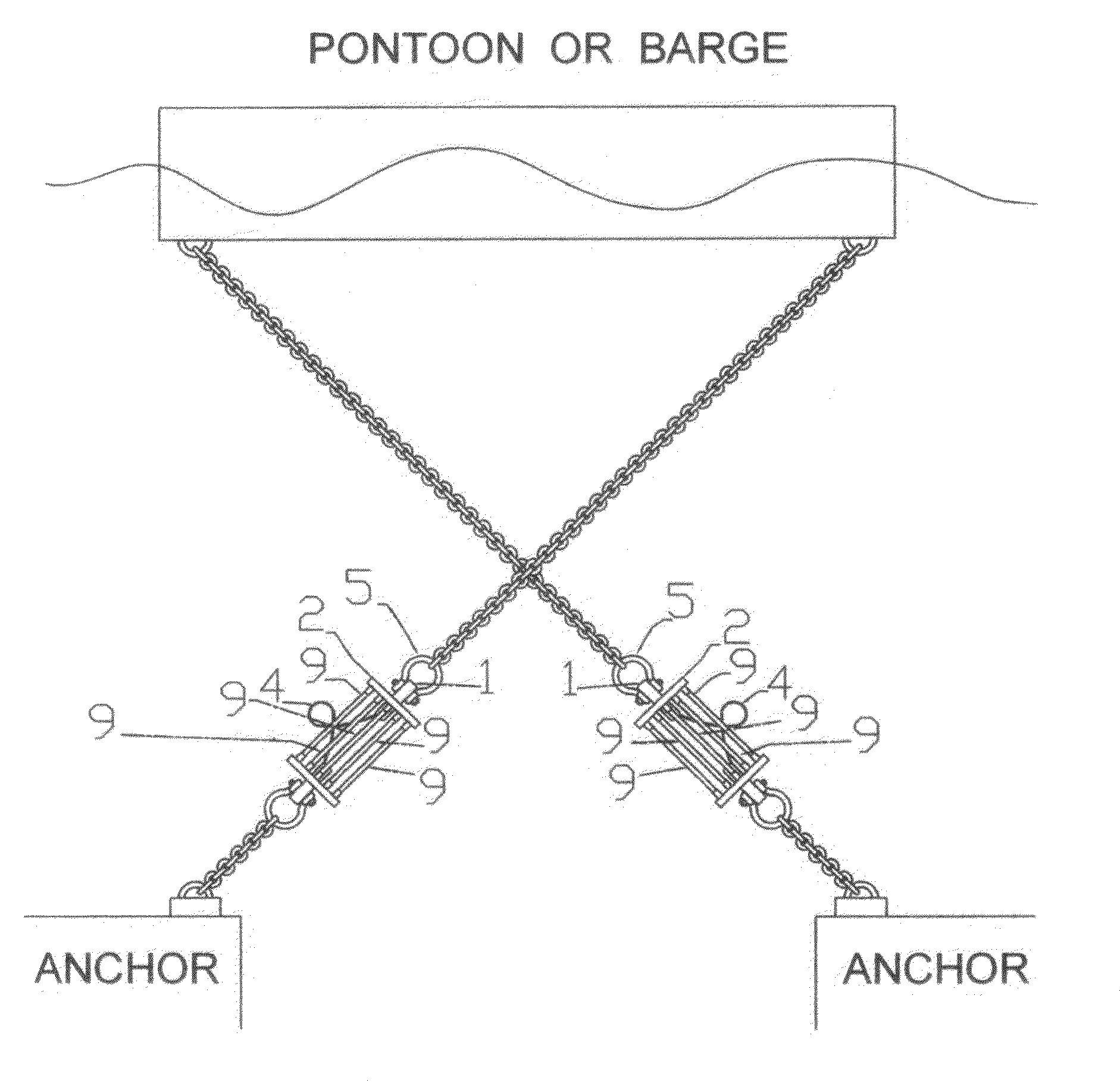
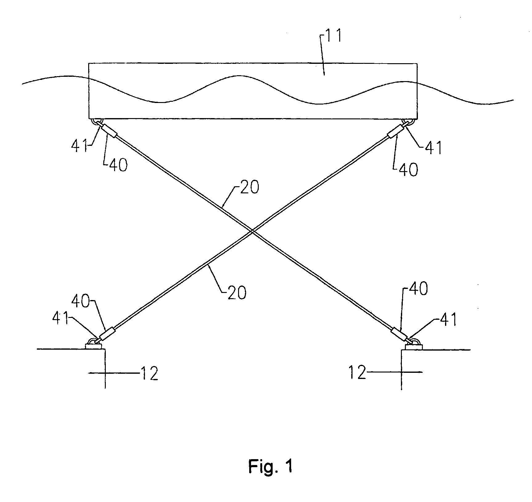
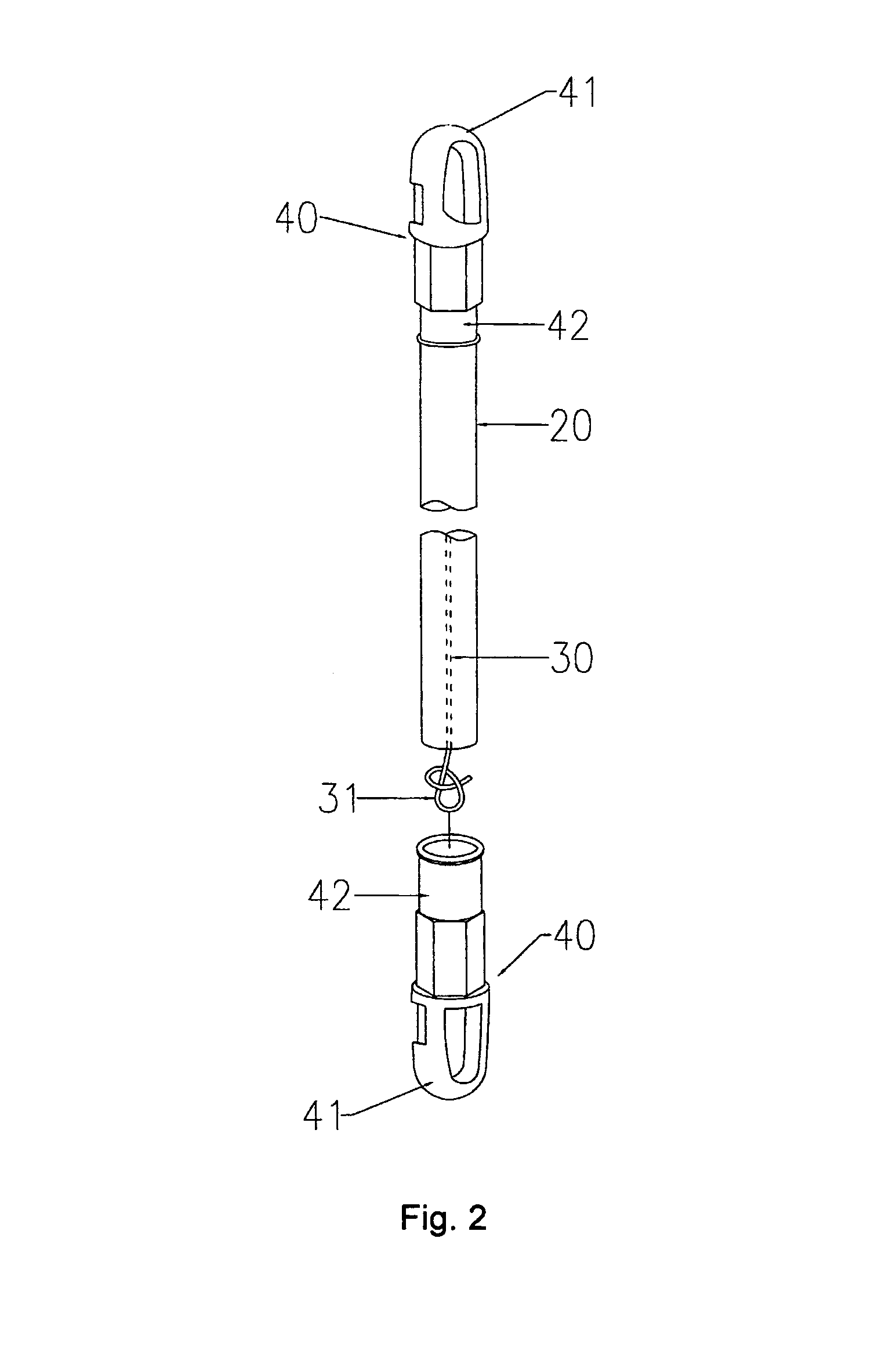
[0021]Referring to FIG. 1 for an anchoring cable 20 holding on to an offshore platform 11 to steadily attached to a submarine anchor 12. The details of layer structure and attachment fixtures are shown in FIGS. 2 to 10. The anchoring cable 20 constitutes a large-sized cable composed of polyurethane elastomer for holding on to an offshore platform 11. The cable 20 includes an outer layer that has multiple layers of polyurethane elastomer and carbon fiber mixed at a certain ratio. The outer layer of the cable 20 is compressed to wrap around an aramid fiber or an ultra-high-molecular-weight polyethylene (UHMWPE) fiber. The cable 20 further includes a core 30 composed of a synthetic fiber with molecular malleability, e.g., nylon, nylon66, and the polyester rope. The core rope 30 is extended on both ends of the cable 20 and exposed and braided in a form as consistent distributed self-locking loop. These self-locking loops are braided in alternative lamination fashion.

[0022]One or multipl...


PUM


Abstract

A new and improved submarine anchoring cable that includes an outer layer that comprises 20% to 80% polyurethane elastomer, 20% to 80% carbon fiber mixed at a certain ratio. The outer layer is compressed to wrap around an aramid fiber or an ultra-high-molecular-weight polyethylene (UHMWPE) fiber and a core of synthetic fiber rope with molecular malleability, e.g., nylon, nylon66, and the polyester rope. The rope is exposed in a form of a loop from both ends of the cable. Each loop has one or multiple layers of sheath made of aramid fiber, Kelvar fiber or UHMWPE fiber wrapping around the rope near a tie on each end to provide extra friction and withstanding strength. One end of the anchor cable is fixed to the offshore platform and the other end is fixed to each anchor to hold on to the offshore platform within a limited area defined by multiple anchors fastened to the offshore platform.

Description

FIELD OF THE INVENTION[0001]The present invention relates to an anchoring cable and fixtures for anchoring and steadily holding an offshore floating platform or pontoon on or in the water. More particularly, the present invention relates to a flexible anchoring rope and improved cable layer configuration and composition materials of anchoring cable and fixture to provide a good pre-stressed buffer to sustain the tension produced by the tidal currents during the rising and ebb tides and a good resilience to keep the floating platform or pontoon in a certain specific area.DESCRIPTION OF THE PRIOR ART[0002]Floating platform anchoring cables (also referred to as tethers, cables, tendons, support lines, mooring lines, and the like) are useful for securing floating structures such floating platforms for different kinds of applications in deepwater. Conventional anchoring cables however are limited by their limited strength to withstand the forces imposed on the platforms by the unpredicta...

Claims


Application Information

Patent Timeline
Patent Type & Authority Patents(United States)
IPC IPC(8): B63B21/00
CPCE02D5/74B63B2021/005
Inventor HUANG, YUN PENG
Owner HUANG YUN PENG
Learn More