Anti-slosh devices for damping oscillation of liquids in tanks

Inactive Publication Date: 2010-01-19
TAYLOR GEOFFREY L
View PDF5 Cites 17 Cited by
  • Summary
  • Abstract
  • Description
  • Claims
  • Application Information

AI Technical Summary

Benefits of technology

[0024]An object of the present invention is to provide anti-slosh devices for damping oscillations of liquids in tanks, the devices being of an appropriate size and shape to be insertable through a fill tube or other access port into the interior of an existing tank, without requiring modification of the tank.
[0029]Another object of the device is to provide an anti-slosh device which is effective in damping oscillations of a liquid in a tank, but which displaces only a small percentage of the volume of the tank.
[0042]It has been found by the present inventor that anti-slosh devices shaped as described above not only provide efficient baffling action which effectively dampens oscillations of a liquid in a tank into which the devices are inserted, but also resist interpenetrating one another, or “nesting” thus enabling a small number of devices to occupy a sufficiently large percentage of the volume of the tank, e.g. one-half, to collectively provide effective dampening of liquid oscillations in the tank.

Problems solved by technology

Liquid oscillations can produce sloshing sounds which are annoying to people close to a tank, as for example, in smaller boats and personal watercraft.
Such oscillations, or sloshing, can result in fatigue wear and ultimate failure of the tank mounts, and support structure.
Even worse, in extreme cases, oscillations of liquid in a vehicle-mounted tank can become so large as to result in loss of steering control and even roll-over of the vehicle.

Method used


Image

  • Anti-slosh devices for damping oscillation of liquids in tanks
  • Anti-slosh devices for damping oscillation of liquids in tanks
  • Anti-slosh devices for damping oscillation of liquids in tanks

Examples


Embodiment Construction

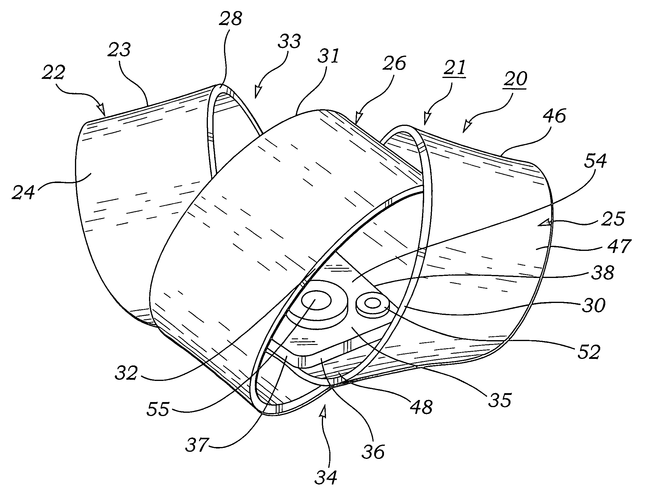
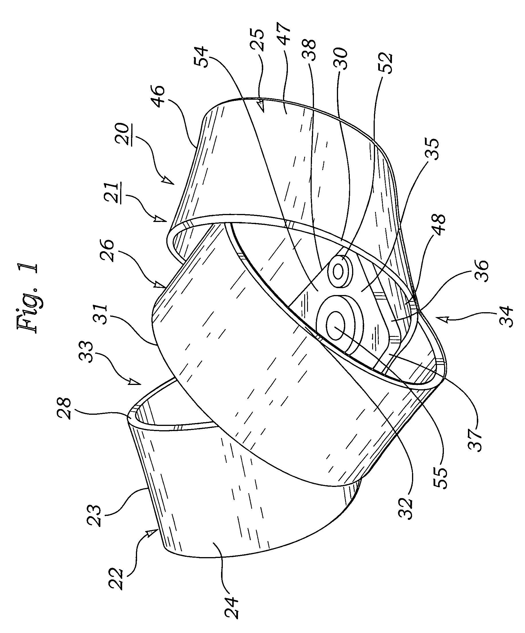
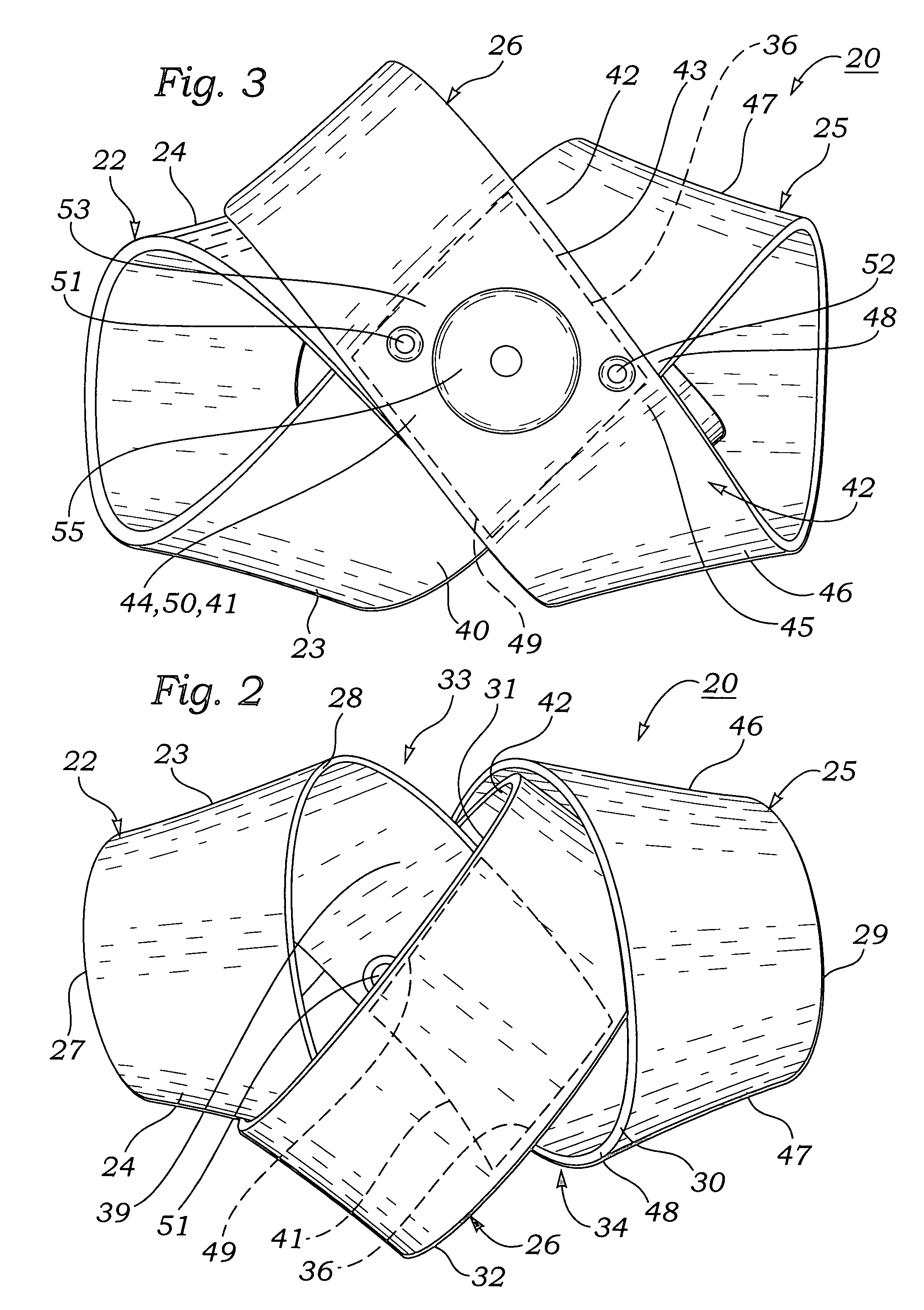
[0055]FIGS. 1-12 illustrate anti-slosh devices for damping oscillations of liquid in tanks, according to the present invention.

[0056]FIGS. 1-7 illustrate a preferred, three-loop embodiment 20 of an anti-slosh device according to the invention. As shown in those figures, anti-slosh device 20 is preferably formed of a single thin, longitudinally elongated rectangularly-shaped strip 21 which has a uniform thickness and is made of a flexible material that is resistant to degradation by liquids of the type which the device is to be immersed in, e.g., water, gasoline, diesel fuel, etc. The present inventor has found that synthetic polymers such as polycarbonate and high density polyethylene plastics are suitable materials from which to fabricate device 20.

[0057]As shown in FIGS. 1-7, anti-slosh device 20 has a shape which can be formed by bending a thin, elongated rectangular strip 21 made of a flexible material such as a polycarbonate or high density polyethylene into a connected sequenc...


PUM


Abstract

An anti-slosh device for attenuating oscillations of liquids in tanks caused by movement of vehicles in which the tank is located comprises an elongated flat, rectangularly, shaped, uniform thickness strip of a liquid impervious material such as polyethylene or polycarbonate which is formed into a string of arcuately curved loops. One embodiment of the device has located at opposite ends thereof spirally-shaped, quasi-helical end loops which form a figure-8 shape, and a center loop disposed obliquely between the end loops. A two-loop version of the device has two end loops but no center loop. The anti-slosh device is used to reduce the duration of undesirable oscillations induced in a liquid in a tank by placing a plurality of the devices in the interior of a tank, as by inserting a plurality of the devices through a fill tube or other access port of the tank. Non-parallel surfaces of the device function as baffles, converting large scale linear motions of liquid in a tank to small scale, energy-dissipating vortices, thus reducing the duration and amplitude of oscillations of liquid in the tank.

Description

BACKGROUND OF THE INVENTION[0001]A. Field of the Invention[0002]The present invention relates to container tanks used in vehicles such as cars, trucks, planes and boats to contain liquids such as water or fuel, which are to be consumed in transit or delivered by the vehicle. More particularly, the invention relates to devices for decreasing the amplitude and duration of fluid oscillations, i.e., sloshings, of a liquid in a tank, which are induced in response to movements of a vehicle in which the tank is mounted.[0003]B. Description of Background Art[0004]Oscillations of a liquid such as water or fuel contained in a tank mounted in a vehicle such as a car, truck, plane or boat are induced in response to inertial accelerations of the vehicle. The natural or resonant frequency of such oscillations is an inverse function of the internal dimensions of the tank and depends to a lesser extent, upon properties of the liquid such as density and viscosity. Liquid oscillations can produce slo...

Claims


Application Information

Patent Timeline
IPC IPC(8): B65D90/52
CPCB60K15/077B60P3/2235B63B17/00B65D90/52Y10T428/24B60K2015/0344B60K2015/0775
Inventor TAYLOR, GEOFFREY L.
Owner TAYLOR GEOFFREY L
Why Eureka
Try Eureka