
Lamp unit of vehicle headlamp

a technology of headlamps and lamps, which is applied in the direction of lighting support devices, instruments, lighting and heating apparatuses, etc., can solve the problems that the remote optical recognizability cannot be sufficiently promoted by the low beam, and the region on the side of the own lane cannot be irradiated remotely, so as to promote the remote optical recognizability

Inactive Publication Date: 2010-01-19
KOITO MFG CO LTD
View PDF5 Cites 19 Cited by
  • Summary
  • Abstract
  • Description
  • Claims
  • Application Information

AI Technical Summary

Benefits of technology

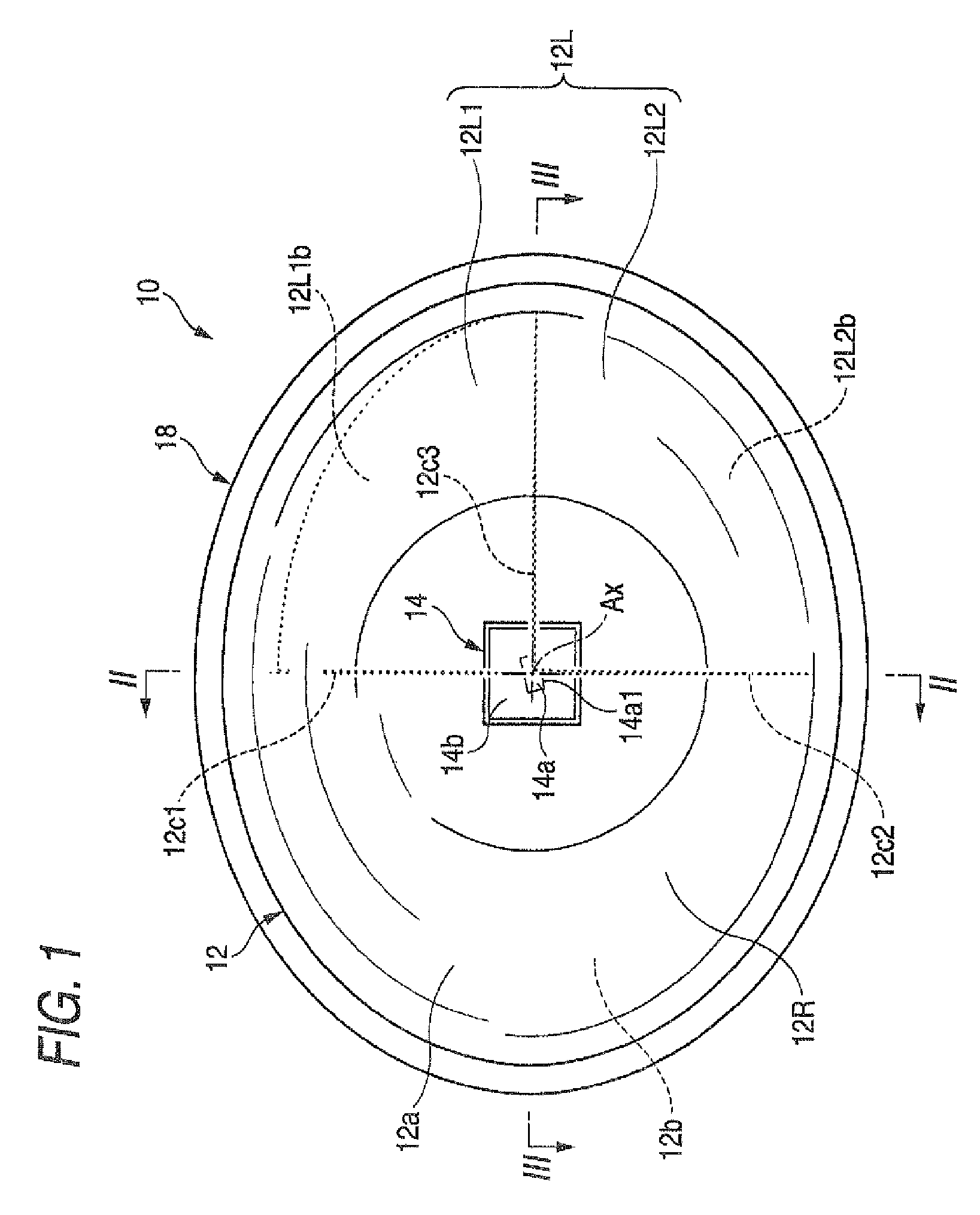
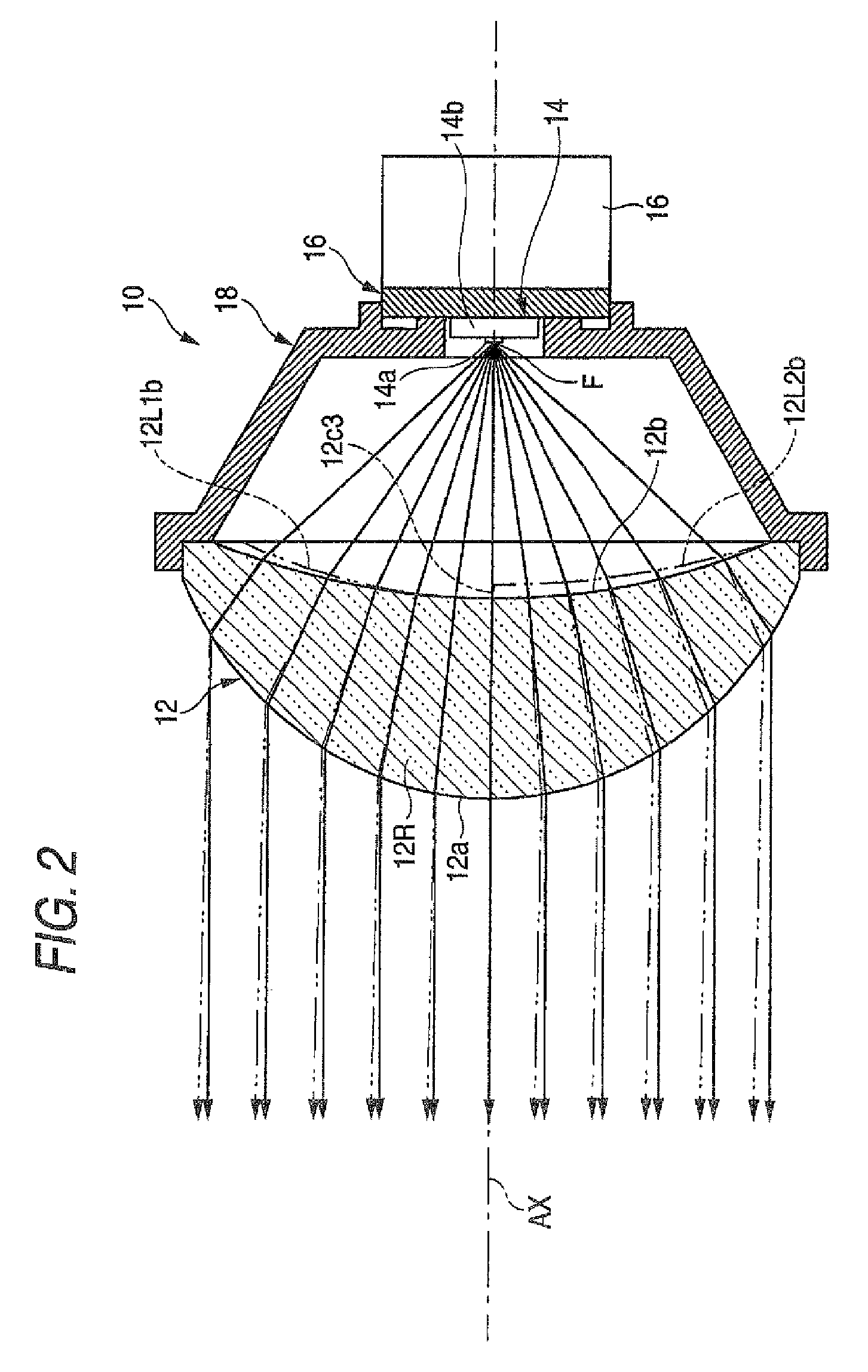
[0010]One or more embodiments of the present invention provide a lamp unit capable of sufficiently promoting a remote optical recognizability by a low beam by irradiating light thereof even when a direct emitting type lamp unit is adopted as a lamp unit of a vehicle headlamp, by devising a shape of a convex lens.
[0018]In this way, according to the one or more embodiments of the present invention, even when the direct emitting type lamp unit is adopted as the lamp unit of the vehicle headlamp, the remote optical recognizability of the low beam can sufficiently be promoted by the irradiating light.
[0019]In the above-described constitution, when there is constructed the constitution of forming a boundary stepped portion partitioning the upper deflecting region and the other lens region on the rear side surface of the convex lens, the front side surface of the convex lens can be constituted by a smooth curve face. Thereby, the above-described operation and effect can be achieved without deteriorating a design performance of the lamp unit.
[0020]In addition, when the boundary stepped portion is formed to step up from the other lens region to the upper deflecting region, light from the light source incident on the boundary stepped portion can be deflected to the side of the one lens region relative to the optical axis. Thereby, it can be prevented beforehand that the light from the light source incident on the boundary stepped portion is emitted to a space at the vicinity of the upper side of the cutoff line on the side of the opposed lane. Thereby, a situation of casting glare light to a driver running on the opposed lane is prevented.
[0021]Moreover, when the light emitting element having the light emitting chip, the lower end edge of which is formed in the linear shape is used as the light source of the lamp unit, an upper end edge of the laterally elongated light distribution pattern can be formed by a high bright / dark ratio as an invertedly projected image of the lower edge of the light emitting chip. Therefore, the laterally elongated light distribution pattern can be formed to be proximate to the cutoff line of the light distribution pattern for the low beam. Thereby, the remote optical recognizability of the vehicle front side road face can further be promoted.

Problems solved by technology

However, even when such a constitution is adopted, the following problem is posed.
Therefore, by only forming the laterally elongated light distribution pattern simply at the vicinity of the lower side of the cutoff line of the light distribution pattern for the low beam, although the vehicle front side road face can be irradiated widely in the width, a region on a side of the own lane cannot be irradiated remotely.
Therefore, there poses a problem that a remote optical recognizability cannot sufficiently be promoted by the low beam.

Method used


Image

  • Lamp unit of vehicle headlamp
  • Lamp unit of vehicle headlamp
  • Lamp unit of vehicle headlamp

Examples


third embodiment

[0091]the invention will be explained.

[0092]FIG. 9 is a front view showing a lamp unit 210 of a vehicle headlamp according to the third exemplary embodiment.

[0093]As shown by the drawing, although a basic constitution of the lamp unit 210 according to the third exemplary embodiment is similar to that in the case of the first exemplary embodiment, a constitution of a light emitting element 214 partially differs from the light emitting element 14 of the first exemplary embodiment. Further, the lamp unit 210 is used in a state of directing the optical axis Ax to a left side by about 2 through 3° more than in the case of the first exemplary embodiment (that is, a state of being directed to a lower side by about 3° relative to an axis line extended in a front and rear direction of a vehicle and directed to a left side by about 2 through 3°).

[0094]Also the light emitting element 214 of the third exemplary embodiment is a white light emitting diode and comprises a light emitting chip 214a ...

fourth embodiment

[0106]the invention will be explained.

[0107]FIG. 11 is a front view showing a lamp unit 310 of a vehicle headlamp according to the fourth exemplary embodiment.

[0108]As shown by the drawing, although a basic constitution of the lamp unit 310 according to the fourth exemplary embodiment is similar to that in the case of the first exemplary embodiment, a position of the light emitting element 14 and a constitution of a convex lens 312 partially differ from those of the case of the first exemplary embodiment.

[0109]According to the fourth exemplary embodiment, the light emitting element 14 is arranged at a position slightly displaced to an upper side from the optical axis Ax. Specifically, a corner portion of the light emitting chip 14a disposed at a lowermost end thereof (that is, a right end portion of the lower end edge 14a1 extended to a left upper side by 15° relative to the horizontal line) is arranged to dispose in a horizontal face including the optical axis Ax.

[0110]Similar to t...


PUM


Abstract

By a convex lens arranged on an optical axis extending in a front and rear direction of a lamp unit, direct light from a light emitting element arranged rearward of the convex lens is deflected to emit so that the light is made to be parallel light in a vertical face and diffused light toward left and right sides in a horizontal face. An entire region of a left side lens region of the convex lens is constituted as upper deflecting regions for deflecting light to a direction upward with respect to a direction of light of a right side lens region. Light emitted to the front side by transmitting the respective upper deflecting regions is made to be light directed upward from light emitted from the right side lens region to thereby form a laterally elongated light distribution pattern in which an upper end edge of a portion of being disposed on a left side relative to the optical axis is stepped up from an upper end edge of a portion thereof disposed on a right side.

Description

[0001]This application claims foreign priority from Japanese Patent Application No. 2006-167595, filed on Jun. 16, 2006, the entire contents of which are hereby incorporated by reference.BACKGROUND OF THE INVENTION[0002]1. Field of the Invention[0003]The present invention relates to a lamp unit of a vehicle headlamp configured to emit direct emitting light from a light source arranged rearward from a convex lens to deflect toward a front side by the convex lens arranged on an optical axis extending in a front and rear direction of the lamp unit.[0004]2. Related Art[0005]In a background art, as a lamp unit of a vehicle headlamp, as described, for example in JP-A-2005-044683, there is known a so-to-speak direct emitting type lamp unit for emitting direct light from a light source arranged rearward of a convex lens to deflect toward a front side by the convex lens arranged on an optical axis extending in a front and rear direction of the lamp unit.[0006]Further, JP-A-2005-108555 descri...

Claims


Application Information

Patent Timeline
Patent Type & Authority Patents(United States)
IPC IPC(8): F21V7/00F21V1/00F21V5/00
CPCF21S48/1154F21S48/1163F21S48/1258F21Y2103/003F21Y2101/02F21Y2103/10F21Y2115/10F21S41/143F21S41/155F21S41/255
Inventor TANAKA, HIDETADA
Owner KOITO MFG CO LTD
Learn More