
Apparatus for supplying energy to a load and a related system

a technology for supplying energy and equipment, applied in the direction of lighting and heating equipment, coupling device connection, instruments, etc., can solve the problems of lack of detail as to energy supply, and the transmission of energy for load devices is not disclosed, so as to avoid eddy current, optimize system efficiency, and reduce the effect of hysteresis loss

Inactive Publication Date: 2010-01-12
LIMPKIN GEORGE A +1
View PDF15 Cites 9 Cited by
  • Summary
  • Abstract
  • Description
  • Claims
  • Application Information

AI Technical Summary

Benefits of technology

"The invention is about using a two-part induction coupling to transmit energy from a high-frequency energy supply to a load. The coupling device is made of a resistive material to avoid eddy currents and low hysteresis, and has low loss to prevent overheating. The frequency range of the invention is between -25 kHz and -10 MHz. The invention also includes a power supply unit, a two-part induction connector, and a load. The two-part connector is designed to hold the parts in relative attitudes to promote efficient inductive coupling. The load can be an incandescent lamp or a fluorescent tube. The invention is safe and can be used in various environments."

Problems solved by technology

U.S. Pat. No. 4,303,902 is also generally similar but discloses the use of ferrite cores and transmission frequencies of e.g. 100 kHz but does not disclose transmission of energy for load devices as opposed to electrical signals e.g. for communications purposes at such frequencies and is devoid of detail as to energy supply.

Method used


Image

  • Apparatus for supplying energy to a load and a related system
  • Apparatus for supplying energy to a load and a related system
  • Apparatus for supplying energy to a load and a related system

Examples


Embodiment Construction

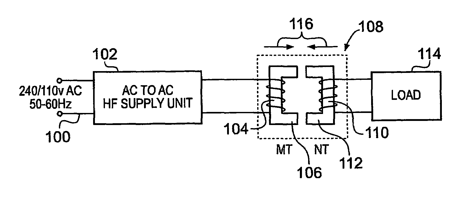
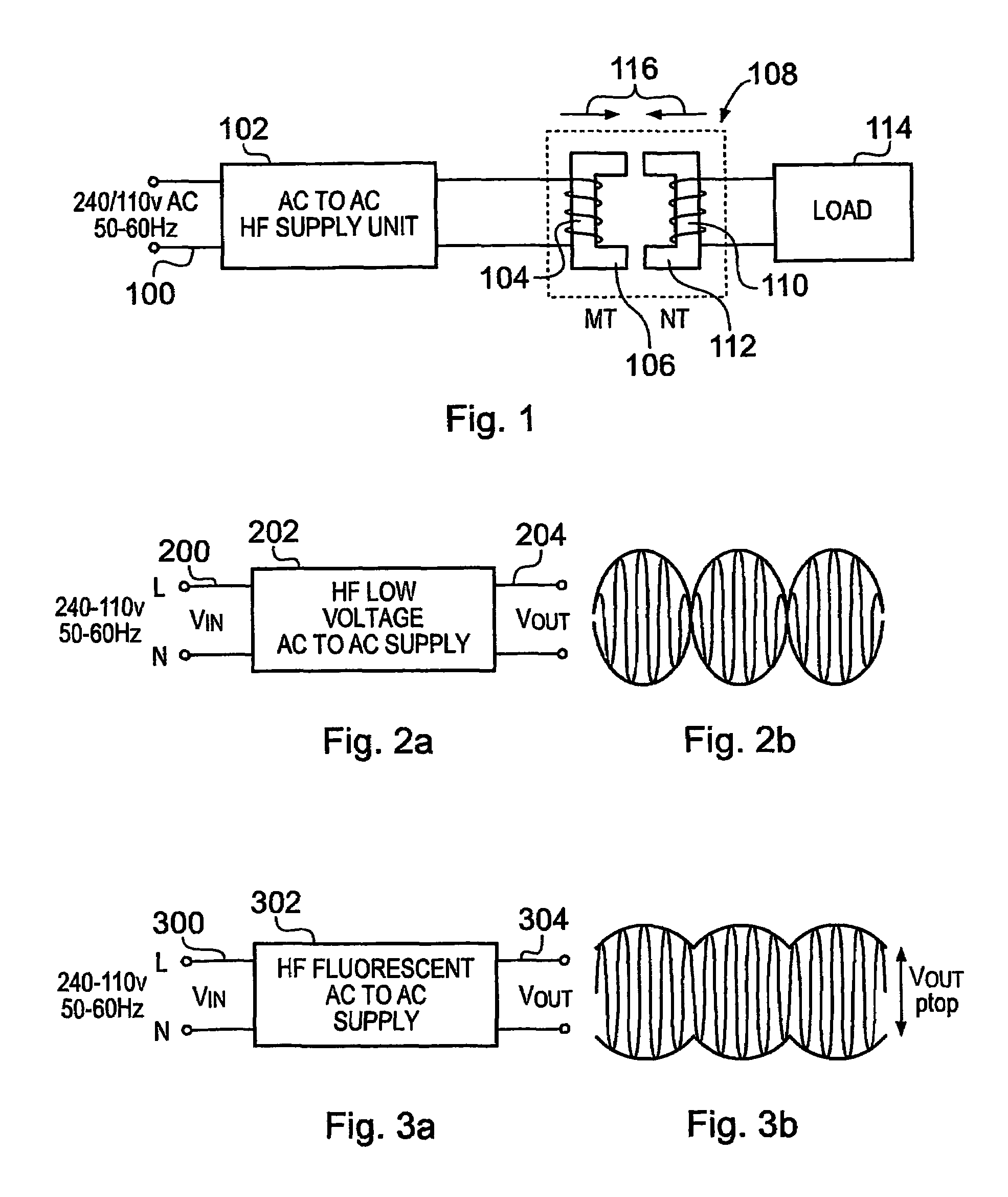
[0061]In FIG. 1, which shows a basic configuration of a power supply arrangement according to the invention, a mains AC supply 100 at e.g. 110 or 240 V and 50-60 Hz supplies energy to a high frequency AC to AC. power supply unit 102 which feeds a primary winding 104 on half-core 106 of a split transformer 108. A secondary winding 110 on half-core 112 is connected to load 114. Examples of loads that might receive energy from the above supply include low voltage halogen lamps, other incandescent lamps, fluorescent lamps, fans, electric motors, detectors, computers, industrial, domestic devices or power distribution circuits e.g. for use in a building or part of a building or for use in outdoor lighting. The contact may be established by mating the two parts, and may be broken by separating them. The parts being relatively movable as indicated by the arrows 116.

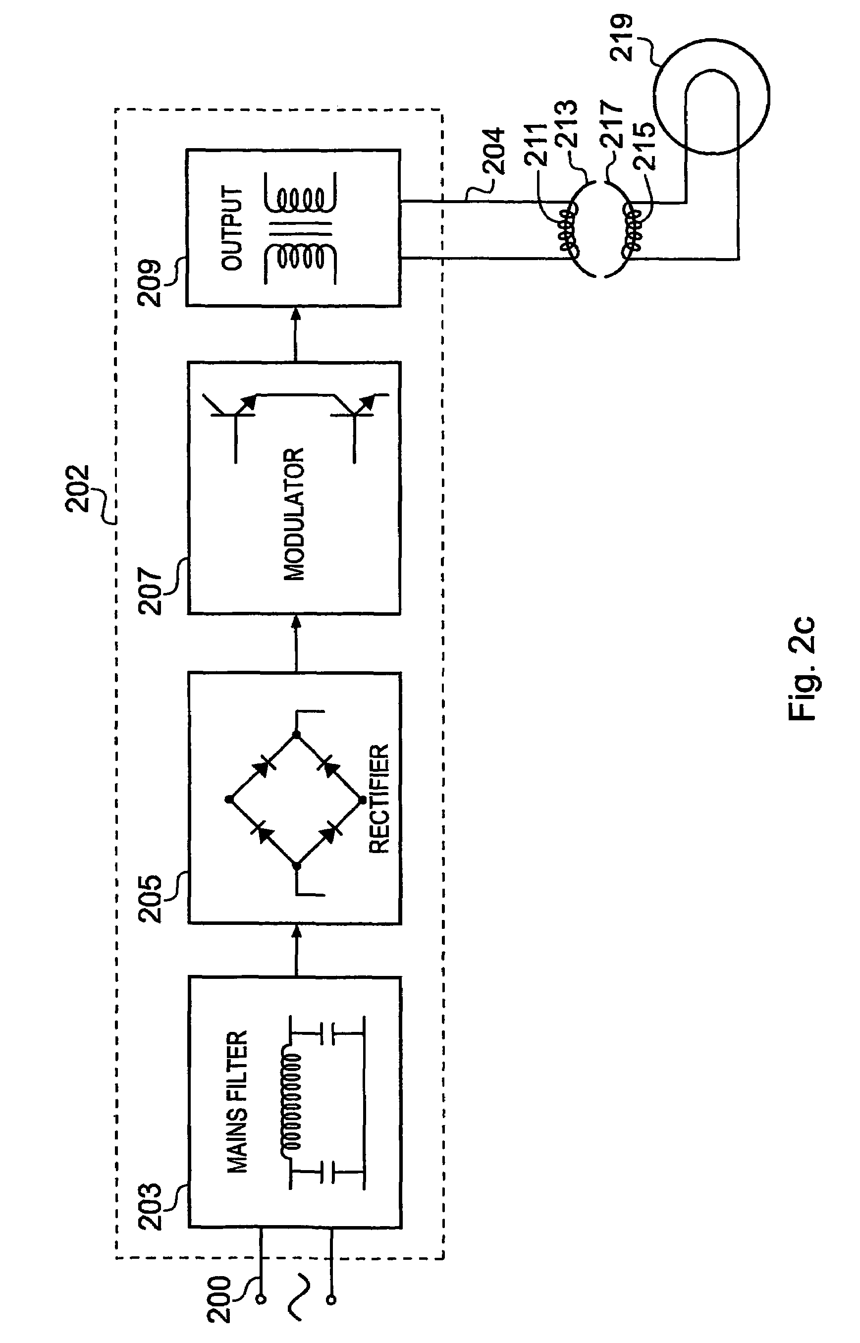
[0062]FIG. 2a shows diagrammatically a high frequency low voltage supply in which electrical energy from supply 200 is fed to ...


PUM

PropertyMeasurementUnit
bulk resistivityaaaaaaaaaa
frequencyaaaaaaaaaa
frequencyaaaaaaaaaa

Abstract

Apparatus for supplying energy to a load, comprises a power supply unit (102) e.g. a switched mode electronic transformer or electronic ballast having an input for receiving current at mains frequency and a means for stepping-up said mains frequency to a higher frequency e.g. 30-50 kHz and an output for delivering energy at the higher frequency. A two part connector (108) has a first core portion (106) that has a primary winding (104) connected to the output of the power supply unit and a mating second core portion (112) that has a secondary winding (110) for delivery of energy to a load (114), the core portions being of a high resistivity material, e.g. a ferrite having a resistivity of at least 104 Ωcm. The apparatus may be used to power e.g. low voltage halogen or other incandescent lighting, fluorescent lighting, or an electric motor, a power supply for a computer, radio, television or like electronic device, a heater or the like.

Description

CROSS-REFERENCE TO RELATED APPLICATIONS[0001]This application is an U.S. national phase application under 35 U.S.C. §371 based upon co-pending International Application No. PCT / GB2004 / 001897 filed on May 4, 2004. Additionally, this U.S. national phase application claims the benefit of priority of co-pending International Application No. PCT / GB2004 / 001897 filed on May 4, 2004 and Great Britain Application No. 0310088.0 filed on May 2, 2003. The entire disclosures of the prior applications are incorporated herein by reference. The international application was published on Nov. 11, 2004 under Publication No. WO 2004 / 097866 A1.FIELD OF THE INVENTION[0002]The present invention relates to an apparatus for supplying energy to a load and a related system. More particularly the invention relates to an electrical energy transmission apparatus including a two-part induction connector as a means of delivering energy to electrical appliances for example: lighting equipment, computers, periphera...

Claims


Application Information

Patent Timeline
Patent Type & Authority Patents(United States)
IPC IPC(8): H01F21/06H01F38/14H02J5/00H02M3/337H05B39/00H05B41/24H05B44/00
CPCH01F38/14H02J5/005H02M3/337H05B33/0803H05B39/00H05B41/245H05B33/0815F21Y2101/02F21V25/12F21Y2115/10H05B45/00H05B45/3725H05B47/00H02J50/40H02J50/10H02M3/33571H02J5/00H02M5/00H02M7/00H01R13/66H02J50/12
Inventor LIMPKIN, GEORGE A.ROZENBERG, SIMON G.
Owner LIMPKIN GEORGE A
Learn More