Pressure relief valve for use in cementitious material pumping systems

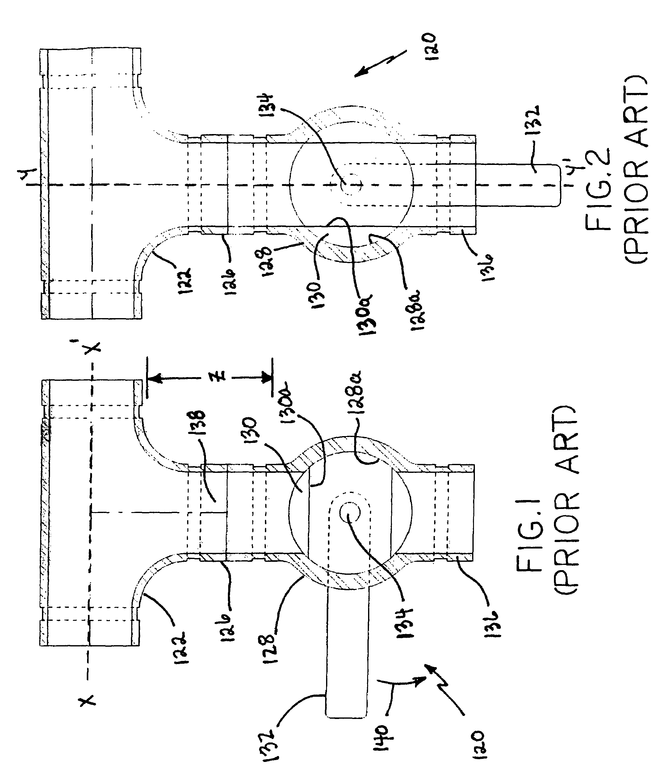
a technology of cementitious materials and pressure relief valves, which is applied in valve housings, mechanical equipment, transportation and packaging, etc., can solve the problems of no internal means to relieve the pressure buildup, the valve is useless, and the material tends to settle out of suspension and agglomera

Inactive Publication Date: 2010-01-12
CHEM GROUTING
View PDF4 Cites 5 Cited by
  • Summary
  • Abstract
  • Description
  • Claims
  • Application Information

AI Technical Summary

Benefits of technology

[0007]Accordingly, it is an object of the present invention to provide for the quick and safe discharge of pressure in a closed system for the pumping of cementitious materials.

Problems solved by technology

However, under pressure, and particularly if the linear velocity is reduced, the materials tend to settle out of suspension and agglomerate within the hose and the discharge portion of the pump.
Due to the ball valve design, there is no internal means to relieve this pressure buildup.
Unfortunately, due to the geometry of these types of valves, there is usually a considerable distance between the flow line and the actual valve mechanism, and often this conduit becomes plugged with material, rendering the valve useless and frequently necessitating its replacement.
As discussed above, one of the problems with this arrangement is the dead space 138 disposed between the conduit-connected portion of the T-connector 122 and the pressure relief valve 120.
This situation makes cleaning of the grout pumping system after use very difficult and may even necessitate replacement of the T-connector 122 and pressure relief valve 120 combination.

Method used


Image

  • Pressure relief valve for use in cementitious material pumping systems
  • Pressure relief valve for use in cementitious material pumping systems
  • Pressure relief valve for use in cementitious material pumping systems

Examples


Embodiment Construction

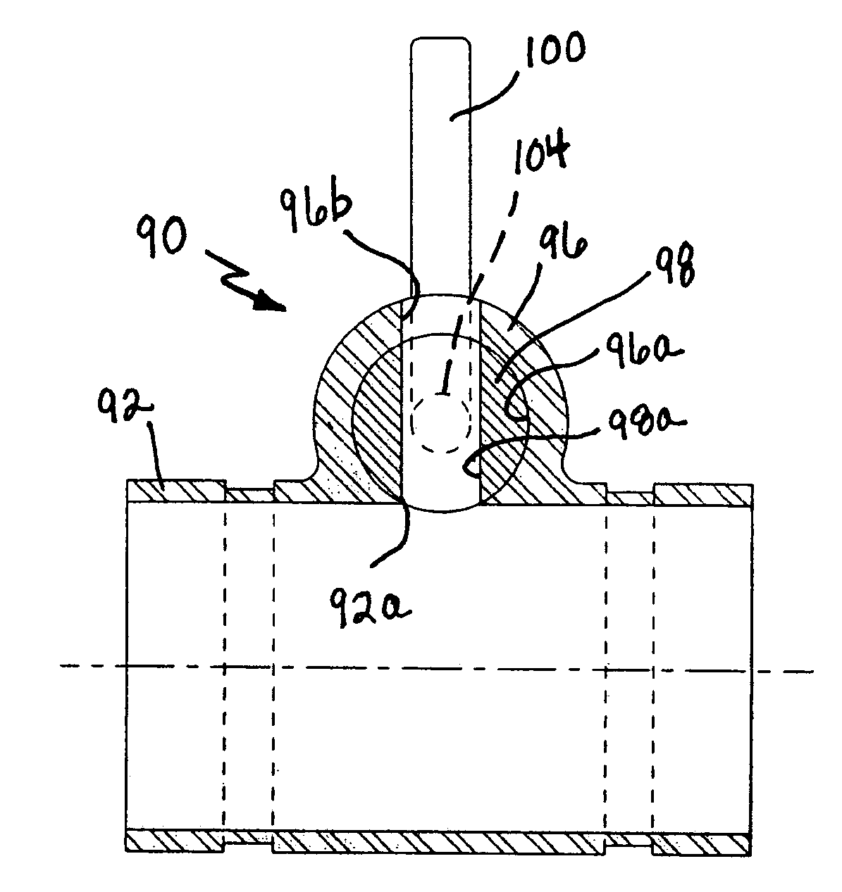
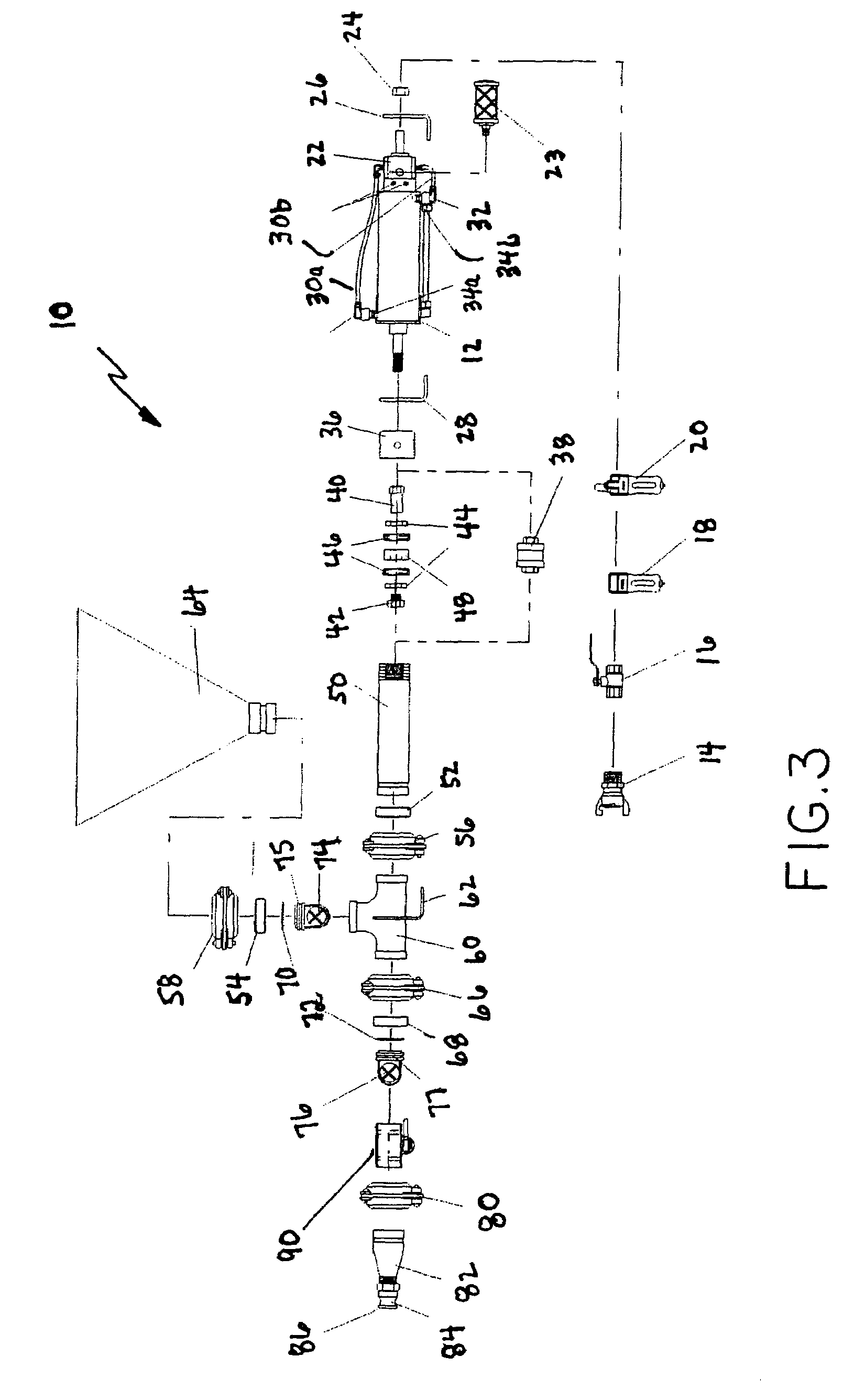
[0018]Referring to FIG. 3, there is shown a side elevation view in exploded form of a cementitious material pumping system 10 in which the pressure relief valve 90 of the present invention is intended for use. In the following description, the term “cementitious material” is intended to include various materials also sometimes referred to as grout, mortar or finishing plaster. The inventive pressure relief valve 90 is not limited to use within the cementitious material pumping system 10 shown in FIG. 3, but has application in virtually any type of high pressure pumping system for use with cementitious materials.

[0019]The cementitious material pumping system 10 includes an air cylinder 12 coupled to a source of air under pressure, i.e., a compressor (which is not shown for simplicity), by means of an air coupling 14, an air valve 16, an air filter 18 and a lubricator 20. A rear cylinder bracket 26 is coupled by means of a rear mount nut 24 to the air cylinder 12 adjacent to where the...


PUM


Abstract

A pressure relief valve integrally formed with a section of conduit in a closed system for pumping cementitious material eliminates any dead space in the system within which the cementitious material may flow and set, and thus avoids system disassembly for cleaning following use and the possible replacement of clogged system components. The pressure relief valve includes a hollow cylindrical housing disposed on a conduit. First and second elongated linear slots are aligned with the cylindrical housing's longitudinal axis and are disposed in opposed portions of housing, with one slot in flow communication with the conduit. A cylindrical drum having a third elongated linear slot disposed within the cylindrical housing is freely rotatable therein. A handle attached to one end of the drum allows for manual rotation of the drum for aligning the three slots permitting the discharge of cementitious material and release of pressure in the system.

Description

FIELD OF THE INVENTION[0001]This invention relates generally to systems for pumping a cementitious material under pressure, and is particularly directed to a hand-operated valve for safely releasing the pressure in a closed pumping system for cementitious materials.BACKGROUND OF THE INVENTION[0002]There are various types of reciprocating pumps used for pumping cementitious materials. A common form that these types of pumps take is that of a ball valve pump; that is, the flow of material through the pump is controlled by an inlet (suction) valve and a discharge valve, each of which consists of a ball and a seat. Thus, on the suction stroke the inlet ball unseats, allowing material to enter the pump housing, while the discharge valve is seated, preventing drawback of previously pumped material. On the discharge (extend) stroke, the discharge valve is forced open and the inlet (suction) valve is seated, thus preventing blowback into the hopper. This action is very simple, but very effe...

Claims


Application Information

Patent Timeline
Patent Type & Authority Patents(United States)
IPC IPC(8): F16K5/00
CPCF16K5/02F16K27/062F16K5/0292Y10T137/86871
Inventor SCHATZ, BEN P.
Owner CHEM GROUTING
Why Eureka
Try Eureka