Optical pickup

a technology of optical pickups and optical beams, applied in the field of optical pickups, can solve the problems of insufficient light, insufficient signal reproduction accuracy, and high cost, and achieve the effects of reducing cost, improving recording/reproduction accuracy, and suppressing unwanted spectral separation

Inactive Publication Date: 2009-12-29
FUNAI ELECTRIC CO LTD
View PDF16 Cites 0 Cited by
  • Summary
  • Abstract
  • Description
  • Claims
  • Application Information

AI Technical Summary

Benefits of technology

[0021]The present invention has been devised to overcome the above-described problems, and its object is to provide an optical pickup which, by using a two-wavelength monolithic laser diode, is capable of ameliorating a reduction in the power of the laser beam, effecting satisfactory recording and reproduction, and attaining a cost reduction of the optical system.

Problems solved by technology

However, this optical axis correcting element 94 is required for the optical system, and one extra element of the optical system is required, leading to a higher cost.
In actuality, however, infinitesimal light is present, and there are cases where a signal from an adjacent track or a nearby track is picked up, so that signal reproduction accuracy becomes inferior.
Hence, there is a tendency of increasing the cost correspondingly.
Hence, there been a problem in that higher cost is entailed correspondingly.
In actuality, however, infinitesimal light is present, and there are cases where a signal from an adjacent track or a nearby track is picked up, so that there is the problem that signal reproduction accuracy becomes inferior.
Hence, there is the problem that the cost increases correspondingly.
However, since the aperture of the objective lens is limited by a liquid-crystal element, the polarizing direction is perpendicular.
As a result, there are cases where a signal from an adjacent track or a nearby track is mixed, so that noise components are superimposed on the reproduction signal.

Method used


Image

  • Optical pickup
  • Optical pickup
  • Optical pickup

Examples


Embodiment Construction

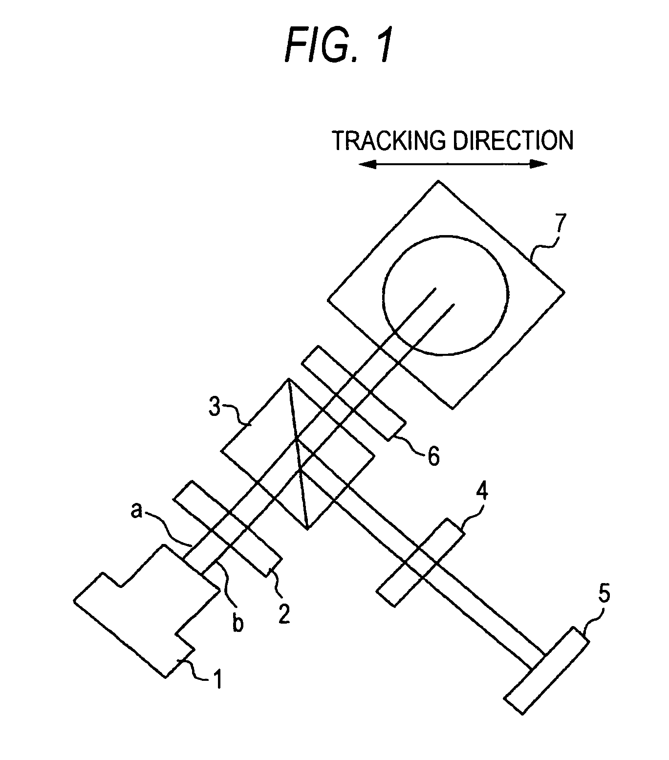
[0057]Referring now to the accompanying drawings, a description will be given of an embodiment of the invention. FIG. 1 is a diagram schematically illustrating the construction of an optical system in an optical pickup in accordance with the embodiment of the invention.

[0058]The optical system of this optical pickup includes a two-wavelength monolithic laser diode 1, a two-wavelength one-sided diffractive element 2, a polarizing beam splitter 3, a cylindrical lens 4, a photodetector 5, a quarter wavelength plate 6, an upper mirror 7, and the like. It should be noted that an objective lens is not shown. The two-wavelength monolithic laser diode 1 used in this optical system is a monolithic laser diode in which the semiconductor chip consists of a single chip, is mounted on an unillustrated mounting base, and emits a laser beam a for CD and a laser beam b for DVD. This two-wavelength monolithic laser diode 1 is not such that two semiconductor chips are mounted on the mounting base and...


PUM

PropertyMeasurementUnit
transverse lengthsaaaaaaaaaa

Abstract

An optical pickup including: a monolithic laser light-emitting unit for emitting a first laser beam and a second laser beam having mutually different wavelengths; an one-sided spectrally separating unit for spectrally separating the first laser beam and the second laser beam; a polarizing unit for allowing the laser beam passed through the one-sided spectrally separating unit to be introduced to an optical disk side and for reflecting reflected light from the optical disk; an astigmatism unit for imparting astigmatism to the reflected light; and a photodetecting unit in which a first laser reflected light-receiving portion is arranged in such a manner as to be offset from a second laser reflected light-receiving portion, wherein an optical system is constructed such that a long-axis direction of an ellipse indicating a light spot on the optical disk becomes oblique with respect to a tracking direction.

Description

BACKGROUND OF THE INVENTION[0001]1. Field of the Invention[0002]The present invention relates to an optical pickup provided in an optical disk recording / reproducing apparatus for effecting the recording and / or reproduction of information with respect to an optical disk such as a compact disk (CD) and a digital versatile disk (DVD), and more particularly to the construction of an optical system in the optical pickup.[0003]2. Description of the Related Art[0004]FIG. 11 is a diagram schematically illustrating the construction of an optical system in a first conventional optical pickup. The optical system of this optical pickup includes a two-wavelength hybrid laser diode 91, a two-wavelength double-sided diffractive element 92, a polarizing beam splitter 93, an optical axis correcting element 94, a photodetector 95, a quarter wavelength plate 96, an upper mirror 97, and the like.[0005]The two-wavelength hybrid laser diode 91 uses two semiconductor chips, is mounted on an unillustrated ...

Claims


Application Information

Patent Timeline
Patent Type & Authority Patents(United States)
IPC IPC(8): G11B7/00G11B7/125G11B7/135H01J40/14
CPCG11B7/1275G11B7/1398G11B7/1378G11B2007/0006
Inventor NAKAMURA, HIROKI
Owner FUNAI ELECTRIC CO LTD
Why Eureka
Try Eureka