
Integrated displacement sensors for probe microscopy and force spectroscopy

a displacement sensor and probe technology, applied in the field of probe microscopy, can solve the problems of hindering the progress in the above areas, lack of speed and sensitivity of the cantilever-based structure of the afm probe and its respective actuation methodology, and the approach has not yet found wide application

Active Publication Date: 2009-12-29
GEORGIA TECH RES CORP
View PDF8 Cites 63 Cited by
  • Summary
  • Abstract
  • Description
  • Claims
  • Application Information

AI Technical Summary

Benefits of technology

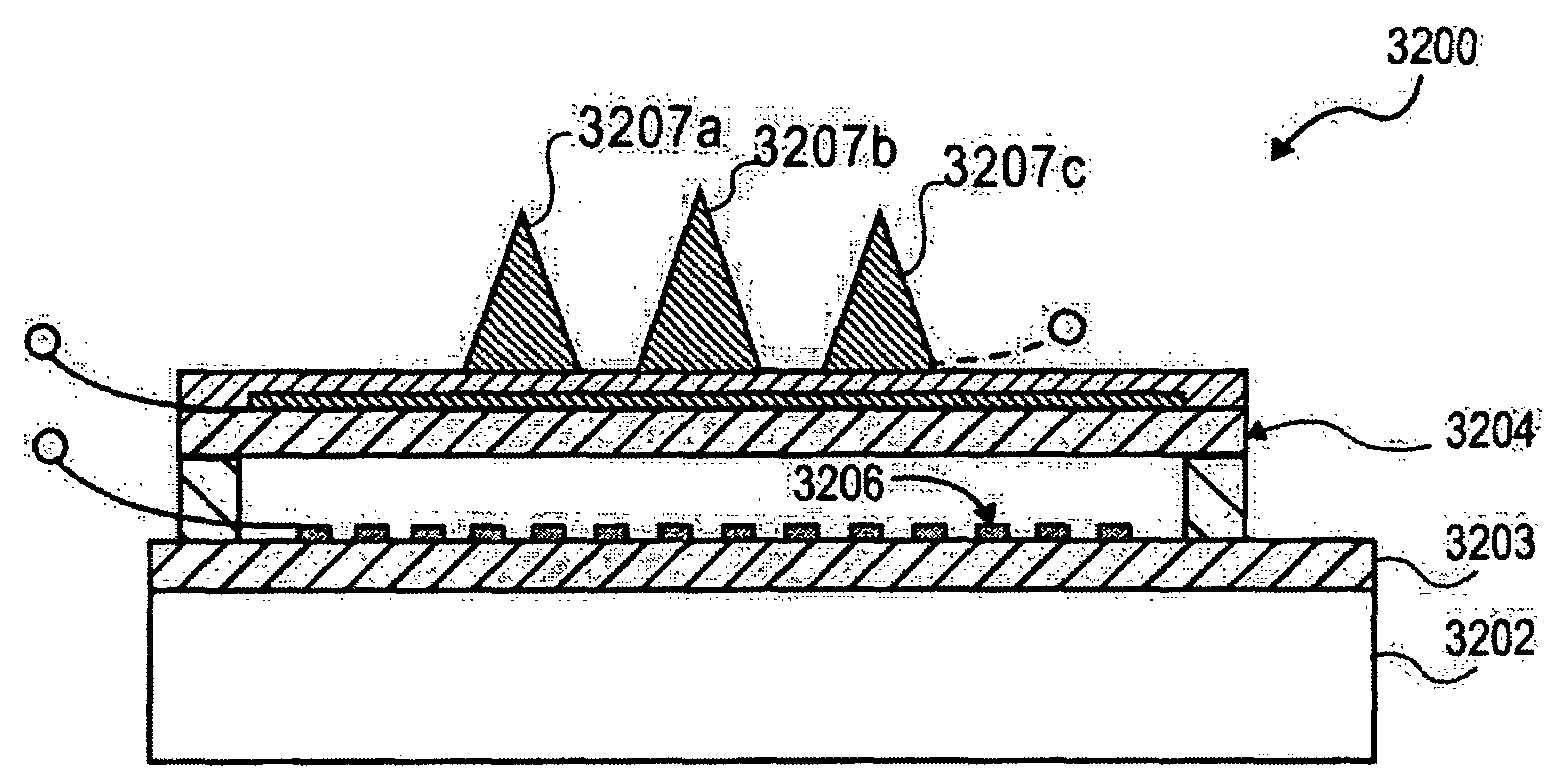
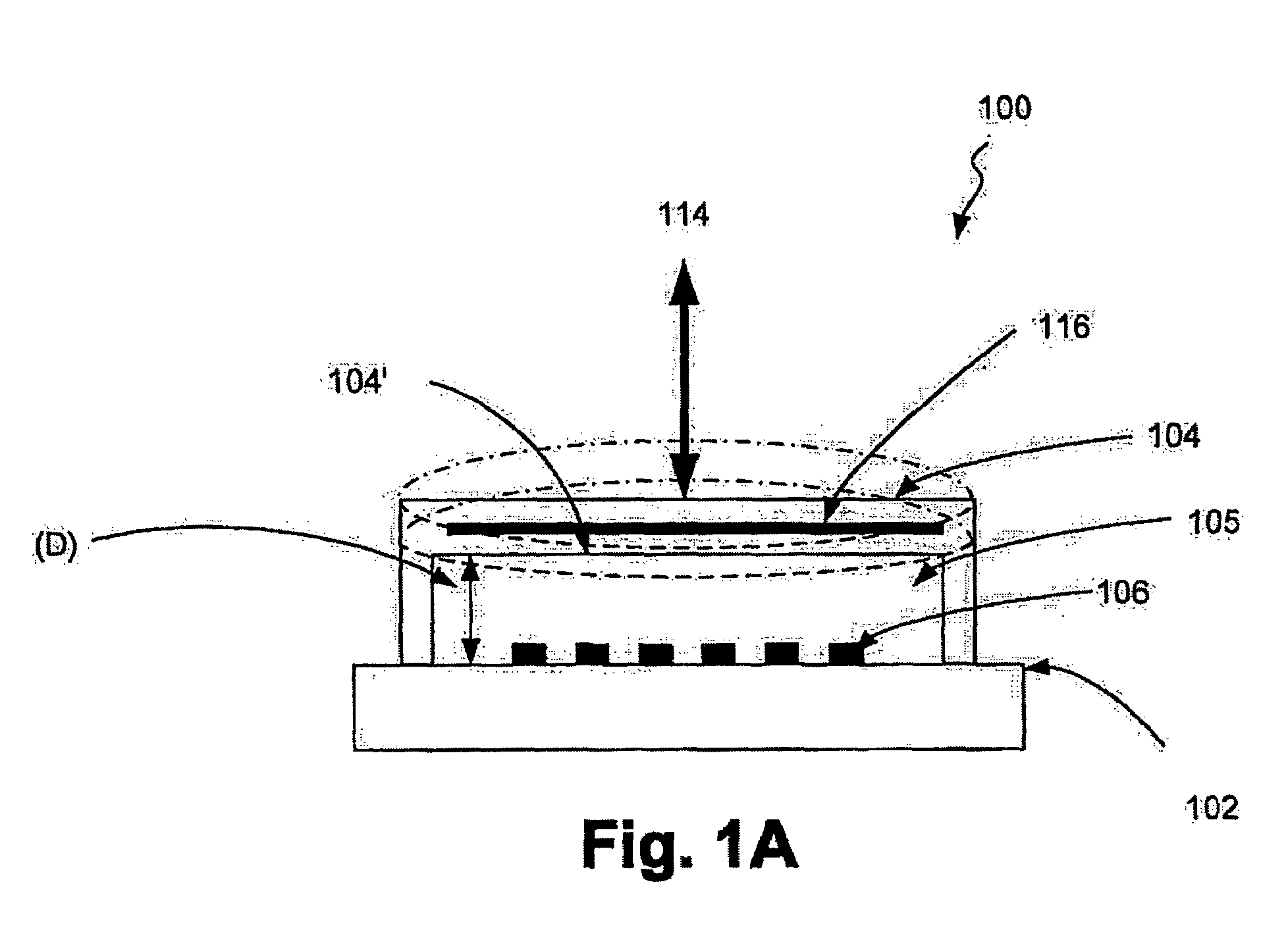
The patent describes a force sensor for a probe based instrument. The sensor has a detection surface and a flexible mechanical structure that deflects when exposed to external force, changing the distance between them. This change in distance can be detected using a detector. The sensor can be used in various instruments to measure force during use. The technical effects of this invention include improved accuracy and sensitivity in measuring force during use of probe based instruments.

Problems solved by technology

Current cantilever-based structures for AFM probes and their respective actuation methodologies lack speed and sensitivity and have hindered progress in the aforementioned areas.
Imaging systems based on small cantilevers have been developed to increase the speed of AFMs, but this approach has not yet found wide use due to demanding constraints on optical detection and bulky actuators.
Several methods have been developed for quantitative elasticity measurements, but the trade-off between force resolution, measurement speed, and cantilever stiffness has been problematic especially for samples with high compliance and high adhesion.
Cantilever deflection signals measured during tapping mode imaging have been inverted to obtain elasticity information with smaller impact forces, but complicated dynamic response of the cantilever increases the noise level and prevents calculation of the interaction forces.
Arrays of AFM cantilevers with integrated piezoelectric actuators have been developed for parallel lithography, but low cantilever speed and complex fabrication methods have limited their use.
This can be quite limiting, as mechanical structures like cantilevers are resonant vibrating structures and they provide information mostly only around these resonances.
For example, in tapping mode imaging it is nearly impossible to recover all the information about the tip-sample interaction force, since the transient force applied at each tap cannot be observed as a clean time signal.
Moreover, conventional methods of imaging with scanning probes can be time consuming while others are often destructive because they require static tip-sample contact.
However, the only free variable in this mode, the phase, is related to the energy dissipation and it is difficult to interpret.
Further, the inverse problem of gathering the time-domain interaction forces from the tapping signal is not easily solvable due to complex dynamics of the AFM cantilever.

Method used


Image

  • Integrated displacement sensors for probe microscopy and force spectroscopy
  • Integrated displacement sensors for probe microscopy and force spectroscopy
  • Integrated displacement sensors for probe microscopy and force spectroscopy

Examples


Embodiment Construction

[0084]In the following description, reference is made to the accompanying drawings that form a part thereof, and in which is shown by way of illustration specific exemplary embodiments in which the invention may be practiced. These embodiments are described in sufficient detail to enable those skilled in the art to practice the invention and it is to be understood that other embodiments may be utilized and that changes may be made without departing from the scope of the invention. The following description is, therefore, not to be taken in a limited sense.

[0085]Notwithstanding that the numerical ranges and parameters setting forth the broad scope of the invention are approximations, the numerical values set forth in the specific examples are reported as precisely as possible. Any numerical value, however, inherently contains certain errors necessarily resulting from the standard deviation found in their respective testing measurements. Moreover, all ranges disclosed herein are to be...


PUM


Abstract

In accordance with an embodiment of the invention, there is a force sensor for a probe based instrument. The force sensor can comprise a detection surface and a flexible mechanical structure disposed a first distance above the detection surface so as to form a gap between the flexible mechanical structure and the detection surface, wherein the flexible mechanical structure is configured to deflect upon exposure to an external force, thereby changing the first distance.

Description

CROSS-REFERENCE TO RELATED APPLICATIONS[0001]This application is a continuation-in-part of U.S. patent application Ser. No. 11 / 260,238, filed Oct. 28, 2005, which claims priority to U.S. Provisional Patent Application Ser. No. 60 / 691,972 filed on Jun. 17, 2005 and U.S. Provisional Patent Application Ser. No. 60 / 707,219 filed on Aug. 11, 2005. This application also claims priority to U.S. Provisional Patent Application Ser. No. 60 / 695,095, filed on Jun. 29, 2005; U.S. Provisional Patent Application Ser. No. 60 / 695,135, filed on Jun. 29, 2005; U.S. Provisional Patent Application Ser. No. 60 / 702,485, filed on Jul. 26, 2005; and U.S. Provisional Patent Application Ser. No. 60 / 703,580, filed on Jul. 27, 2005. The disclosure of the parent application Ser. No. 11 / 260,238 and all of the provisional applications listed above are herein incorporated by reference in their entirety.FIELD OF THE INVENTION[0002]The subject matter of this application relates to probe microscopy. More particularly,...

Claims


Application Information

Patent Timeline
Patent Type & Authority Patents(United States)
IPC IPC(8): G01B5/28G01B11/00G12B21/00G01Q20/02G01Q60/38
CPCB82Y35/00G01Q60/38G01Q20/02
Inventor DEGERTEKIN, F. LEVENTONARAN, ABIDIN GUCLU
Owner GEORGIA TECH RES CORP
Learn More