
High-repetition-rate femtosecond regenerative amplification system

a regenerative amplification and high repetition rate technology, applied in wave amplification devices, electrical equipment, laser details, etc., can solve the problems of 100 khz lasers with very low output power, unable to solve the problem of amplification, and commercial lasers with 100 khz repetition rate have not been used so often

Inactive Publication Date: 2009-12-08
GWANGJU INST OF SCI & TECH
View PDF18 Cites 8 Cited by
  • Summary
  • Abstract
  • Description
  • Claims
  • Application Information

AI Technical Summary

Benefits of technology

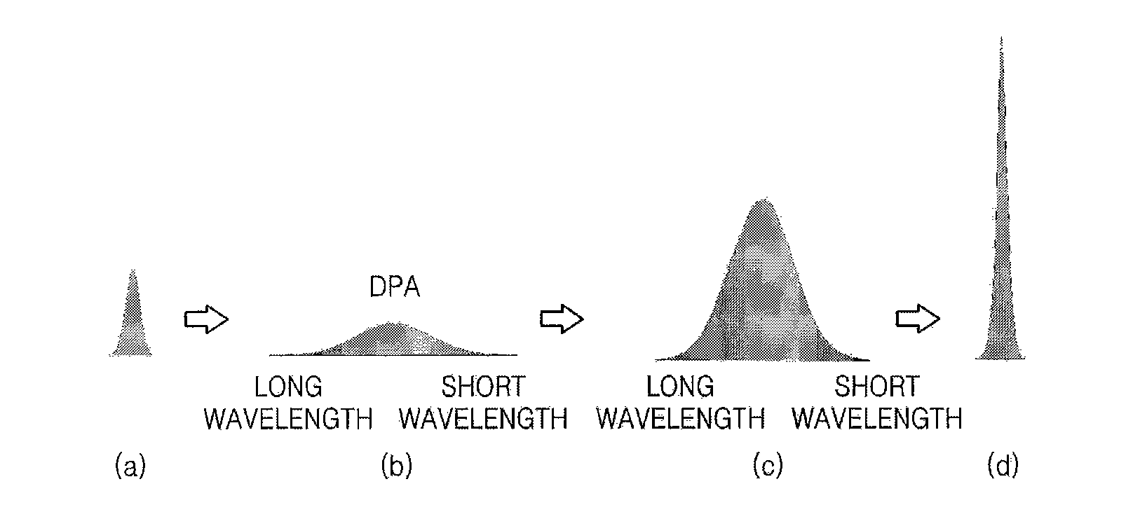
The present invention provides a femtosecond regenerative amplification system that can emit pulses with high output energy. The system includes a laser oscillator, a stretcher, a regenerative amplifier, and a compressor. The pump laser is a high-repetition-rate pulsed green laser or a frequency-doubled Nd:YAG, Nd:YVO4, Yb:YAG laser. The laser oscillator may be a titanium sapphire femtosecond laser or a laser that can generate femtosecond pulses in a wavelength range of 650-1110 nm of a Ti:S gain medium. The gain medium is a Ti:S gain medium. The at least one chirped mirror compensates for dispersion in the resonator. The stretcher stretches the pulses by providing negative dispersion to the pulses. The regenerative amplifier amplifies the pulses and has a repetition rate of 20 to 200 kHz. The pulses are output from the compressor at a repetition rate less than 100 kHz with an energy of 20 μJ or more per pulse.

Problems solved by technology

However, this quest was blocked since high intensities were found to affect the optical properties of lasing materials and optical components.
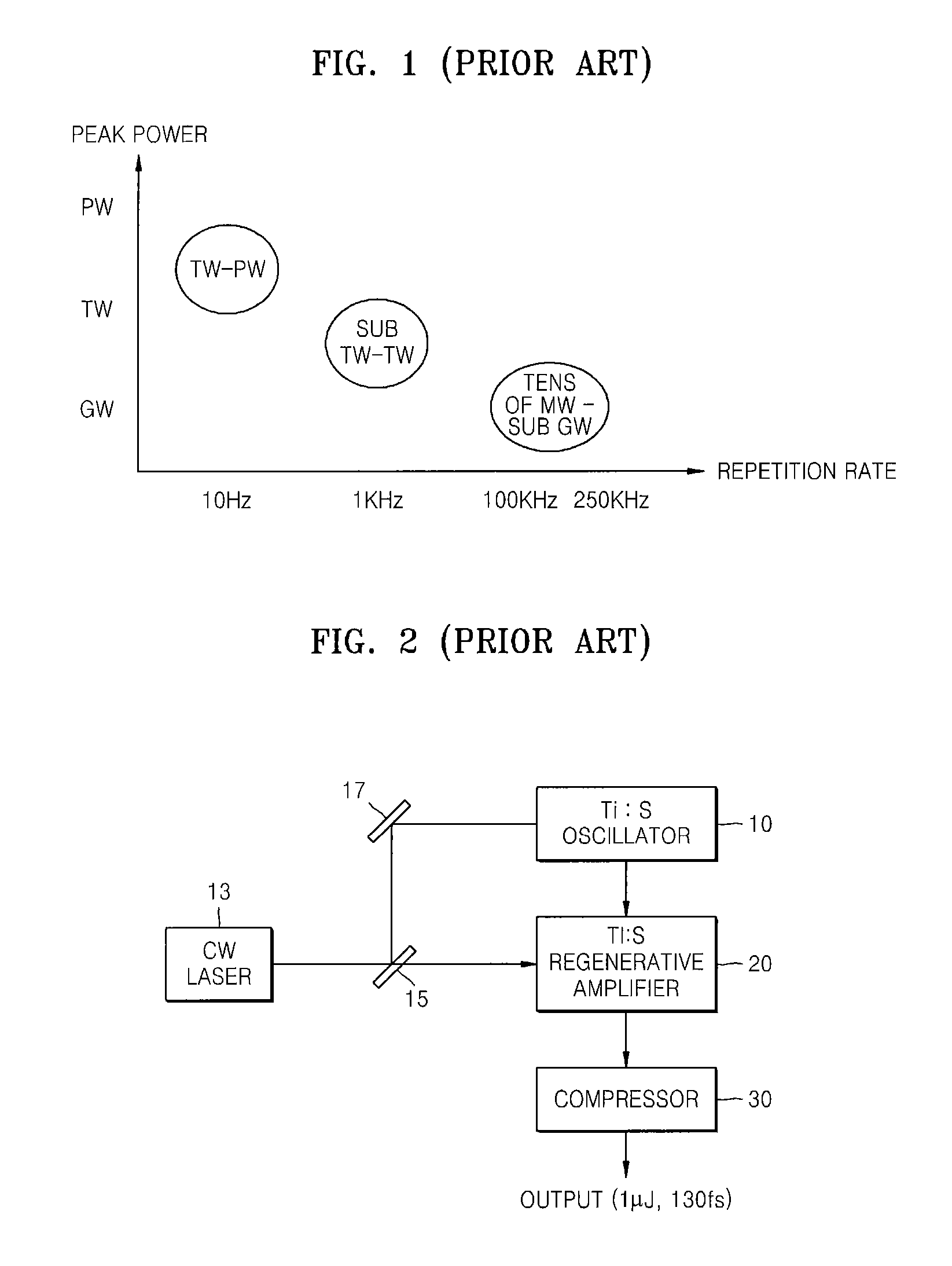
However, compared to 1 to 10 kHz femotosecond lasers, 100 kHz lasers have a very low output power.
As a result, commercial lasers of ˜100 kHz repetition rate have not been frequently used so far.
Furthermore, remaining high order dispersion degrades a compression ratio, thereby making it difficult to produce short pulses less than 100 femtoseconds.
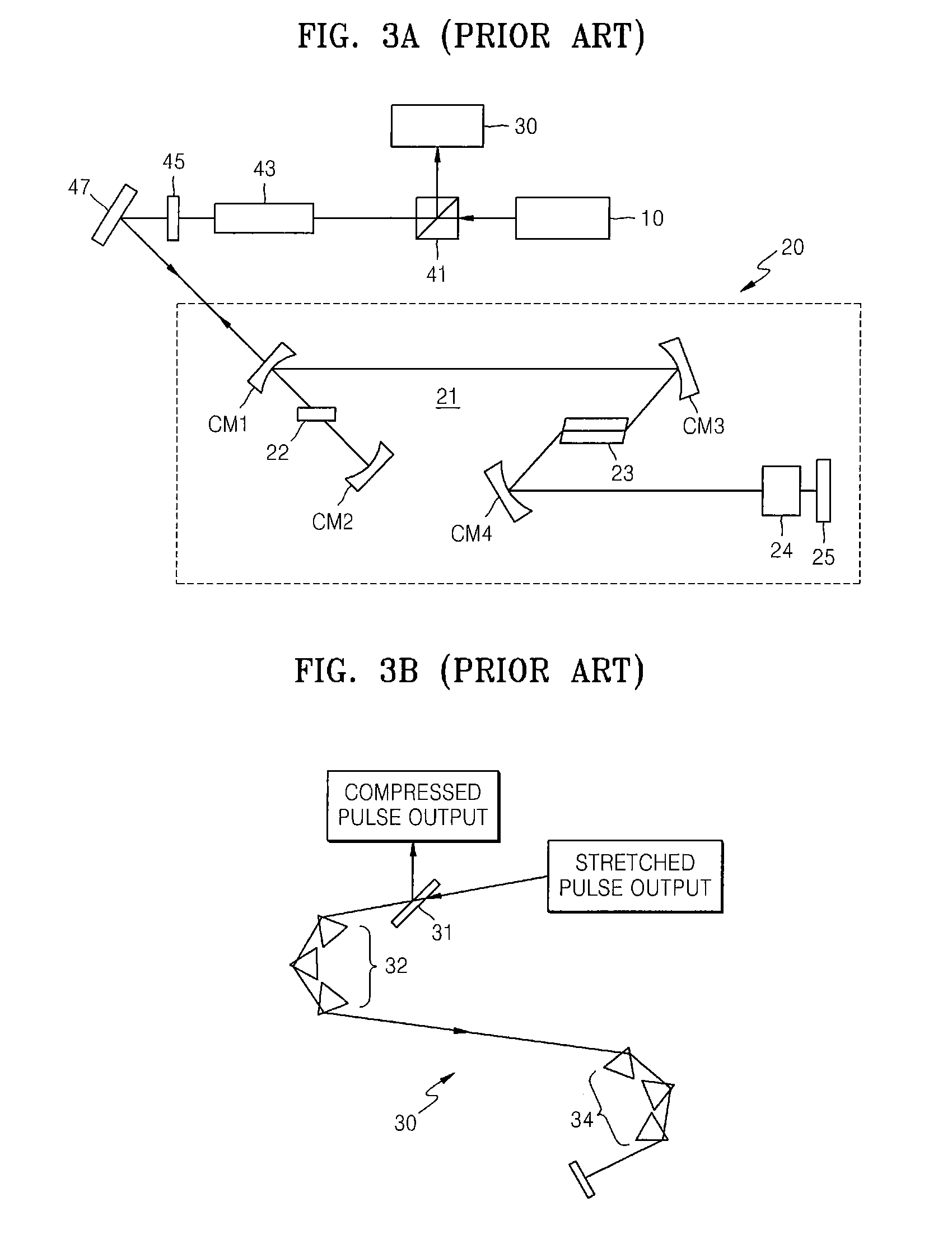
However, the CPA scheme has disadvantages in that because the pluses pass four times through the diffraction gratings during the pulse compression mode, compression efficiency is lowered to 60% or less.

Method used


Image

  • High-repetition-rate femtosecond regenerative amplification system
  • High-repetition-rate femtosecond regenerative amplification system
  • High-repetition-rate femtosecond regenerative amplification system

Examples


Embodiment Construction

[0037]The present invention will now be described more fully with reference to the accompanying drawings, in which exemplary embodiments of the invention are shown.

[0038]FIG. 5 is a plan view of a high-repetition-rate femtosecond regenerative amplification system according to an embodiment of the present invention. Referring to FIG. 5, the regenerative amplification system includes an oscillator 100 outputting laser pulses, a stretcher 200 stretching the output pulses, an amplifier 300 amplifying the stretched pulses, and a compressor 400 compressing the amplified pulses.

[0039]The oscillator 100 may be an ultra-short pulse laser, such as titanium sapphire (Ti:S) femtosecond laser, or a fiber laser that can generate femtosecond pulses in a wavelength range of 650-1100 nm of a Ti:S gain medium. The oscillator 100 outputs pulses to the stretcher 200. The stretcher 200 includes at least one prism, and a pair of diffraction gratings 217 and 220, and stretches the pulses to tens of picose...


PUM


Abstract

Provided is a high-repetition-rate femtosecond regenerative amplification system. The regenerative amplification system includes: a laser oscillator emitting pulses; a stretcher stretching the pulses with negative dispersion; a regenerative amplifier amplifying the pulses, the regenerative amplifier comprising an acousto-optic modulator for pulse switching, a pulsed pump laser for pumping a gain medium, a resonator for reciprocating the pulses between a plurality of mirrors, and at least one chirped mirror for providing negative dispersion; and a glass compressor compressing the pulses. Accordingly, the 100 kHz-class high-repetition-rate femtosecond regenerative amplification system can produce an output energy of tens of μJ, higher than a few μJ provided by a conventional system.

Description

CROSS-REFERENCE TO RELATED PATENT APPLICATION[0001]This application claims the benefit of Korean Patent Application No. 10-2005-0105068, filed on Nov. 3, 2005, in the Korean Intellectual Property Office, the disclosure of which is incorporated herein in its entirety by reference.BACKGROUND OF THE INVENTION[0002]1. Field of the Invention[0003]The present invention relates to a high-repetition-rate femtosecond regenerative amplification system, and more particularly, to a femtosecond regenerative amplification system which can amplify pulses at a high repetition rate of about 100 kHz and produce pulses of a high energy of tens of microjoules (μJ) and a gigawatt (GW) peak power.[0004]2. Description of the Related Art[0005]Lasers have found innumerable applications using their characteristics such as monochromaticity, directionality, and brightness. From the beginning, researches have sought to increase the peak power of their lasers through Q-switching, mode-locking, or amplification. ...

Claims


Application Information

Patent Timeline
Patent Type & Authority Patents(United States)
IPC IPC(8): H01S3/117
CPCH01S3/0057H01S3/094H01S3/235H01S3/1636H01S3/1625
Inventor HONG, KYUNG HANYU, TAE JUNKO, DO KYEONGLEE, JONG MIN
Owner GWANGJU INST OF SCI & TECH
Learn More