Low-light specimen image pickup unit and low-light specimen image pickup apparatus

a low-light specimen and pickup unit technology, applied in the direction of fluorescence/phosphorescence, television systems, instruments, etc., can solve the problems of limited observation time and easy damage of specimens

Active Publication Date: 2009-12-08
EVIDENT CORP
View PDF12 Cites 8 Cited by
  • Summary
  • Abstract
  • Description
  • Claims
  • Application Information

AI Technical Summary

Benefits of technology

[0048]According to the low-light specimen image pickup unit and the low-light specimen image pickup apparatus of the present invention, even in a case of a specimen emitting a low light such as a cell into which luciferase genes are introduced as luminous pigments, it is possible to take an image of the specimen for a short time of exposure without photon counting by a cooled CCD camera at a relatively high temperature of about 0° C.

Problems solved by technology

In observation using a GFP, because the GFP is protein generating fluorescence in accordance with irradiation of an excitation light, and fluorescence is obtained by irradiating a high-intensity excitation light onto a specimen on which the GFP has been acted, the specimen is easily damaged, and an observation time is limited to about one or two hours.
However, in observation using a luciferase, because a light quantity cannot be increased by an excitation light, it is necessary to observe a specimen with low light from the luciferase.

Method used


Image

  • Low-light specimen image pickup unit and low-light specimen image pickup apparatus
  • Low-light specimen image pickup unit and low-light specimen image pickup apparatus
  • Low-light specimen image pickup unit and low-light specimen image pickup apparatus

Examples


embodiment 1

[0156]First, a low-light specimen image pickup unit according to an embodiment 1 of the present invention will be described. FIG. 1 is a schematic diagram showing a structure of the low-light specimen image pickup unit according to the embodiment 1. As shown in FIG. 1, the low-light specimen image pickup unit according to the embodiment 1 has, along an optical axis OA, a specimen 1 serving as an object to be observed and emitting a low light, an image pickup lens 2 serving as an imaging optical system, an infrared light cut filter 4 shading infrared light, and a CCD 3 which is a solid-state image pickup device serving as an image pickup unit.

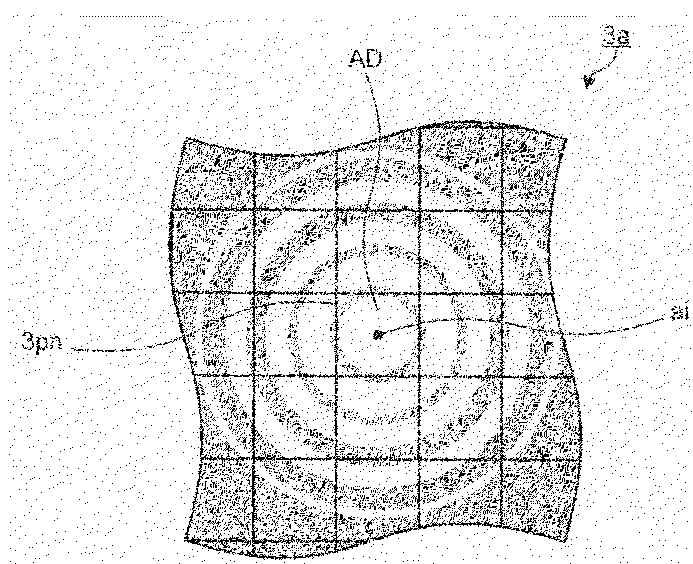
[0157]The image pickup lens 2 detects light from respective point light sources within a predetermined visual field on the specimen 1 at numerical aperture NAo, and forms an image of the specimen 1 onto the imaging area 3a of the CCD 3 perpendicular to the optical axis OA1 so as to be telecentric at numerical aperture NAi. The image pickup lens ...

embodiment 2

[0174]Next, an embodiment 2 of the present invention will be described. In the embodiment 1 described above, an image of the specimen 1 is imaged on the imaging area 3a by the image pickup lens 2 serving as an integrated finite lens system. In the embodiment 2, an image of the specimen 1 is imaged by an infinite lens system formed from an objective lens and an imaging lens.

[0175]FIG. 6 is a schematic diagram showing a structure of a low-light specimen image pickup unit and a low-light specimen image pickup apparatus according to the embodiment 2 of the present invention. As shown in FIG. 6, the low-light specimen image pickup unit according to the embodiment 2 has an objective lens 6 and an imaging lens 7 serving as an imaging optical system, which are disposed along an optical axis OA2, the infrared light cut filter 4, and the CCD 3. Here, component parts which are the same as those in the embodiment 1 are denoted by the same reference numerals.

[0176]The objective lens 6 is held wi...


PUM

PropertyMeasurementUnit
sizesaaaaaaaaaa
temperatureaaaaaaaaaa
lengthaaaaaaaaaa

Abstract

In order to be able to take an image of a specimen emitting low light in a short exposure time by a cooled CCD at about 0° C., a low-light specimen image pickup unit has an imaging optical system forming a specimen image of a specimen having a point light source emitting a low light, and the low-light specimen image pickup unit further has an image pickup unit having a plurality of pixels receiving incident light, for taking an image corresponding to the specimen image. In the low-light specimen image pickup unit, the imaging optical system is telecentric to a side of the specimen image of the imaging optical system, and condenses the low light emitted from the point light source to form an Airy disk of a size which is substantially the same as a pixel of the pixels, or which is smaller than the pixel. Here, the pixel receives the low light emitted from the point light source.

Description

TECHNICAL FIELD[0001]The present invention relates to a low-light specimen image pickup unit and a low-light specimen image pickup apparatus which take an image of a specimen emitting a low light, and in particular, to a low-light specimen image pickup unit and a low-light specimen image pickup apparatus which are suitable for being applied to taking an image of a specimen having minute luminescent sources such as a specimen generating low fluorescence or a biological fluorescent specimen.BACKGROUND ART[0002]In recent years, in the research field of cell biology, molecular biology, and the like, the necessity to observe biological cells such that a green fluorescent protein (GFP; Green Fluorescent Protein) or a luciferase gene which is a bioluminescent enzyme is made to function as a reporter of expression, and a fluorescent sign or a luminescent sign is attached to a specific portion or a functional protein in a cell, has grown.[0003]In observation using a GFP, because the GFP is p...

Claims


Application Information

Patent Timeline
Patent Type & Authority Patents(United States)
IPC IPC(8): G02B21/36G01N21/00G01N21/64G03B17/12
CPCG02B13/22H04N5/2254G02B21/361G02B21/16H04N23/55
Inventor SUZUKI, HIROBUMIDOSAKA, SHINICHI
Owner EVIDENT CORP
Why Eureka
Try Eureka