Micromechanical actuator with asymmetrically shaped electrodes
a micromechanical actuator and electrode technology, applied in the direction of generator/motor, relay, instrument, etc., can solve the problems of impracticality in practice, inability to provide good deflection characteristics of the actuator, and all previous solutions have serious drawbacks, and achieve the effect of minimal actuation for
- Summary
- Abstract
- Description
- Claims
- Application Information
AI Technical Summary
Benefits of technology
Problems solved by technology
Method used
Image
Examples
second embodiment
[0051]Turning next to FIG. 6, the current invention is presented for reduction of rotation due to both elevation during manufacture and actuation is illustrated schematically. A first set of bimorph flexures 601 is affixed to the substrate 600 by anchor points 603. Next, the bimorph flexures 601 are connected to an intermediate frame 605 via an attachment portion 607. Third, a second set of bimorph flexures 609 is connected to the intermediate frame 605 via attachment portions 610. Fourth, the second set of flexures 609 is connected to the actuator platform 612 or directly to the actuator segment itself (not shown) via attachment portions 611.
[0052]The elevation / deflection of the bimorph flexures causes their length projected on to the plane of the substrate to contract. Deflection of the first set of bimorph flexures 601 induces the intermediate frame 605 to rotate clockwise. Likewise, the deflection of the second set of bimorph flexures 609 induces a counterclockwise rotation betw...
first embodiment
[0053]As with the first embodiment, actuation is achieved using three electrodes 615 beneath the platform 611 to impart piston as well as tilting rotation to the actuator. One of the three electrodes can be seen in the side view of FIG. 7. A silicon mirror segment 613 is attached to the top of the actuator to provide a flat, reflective surface.
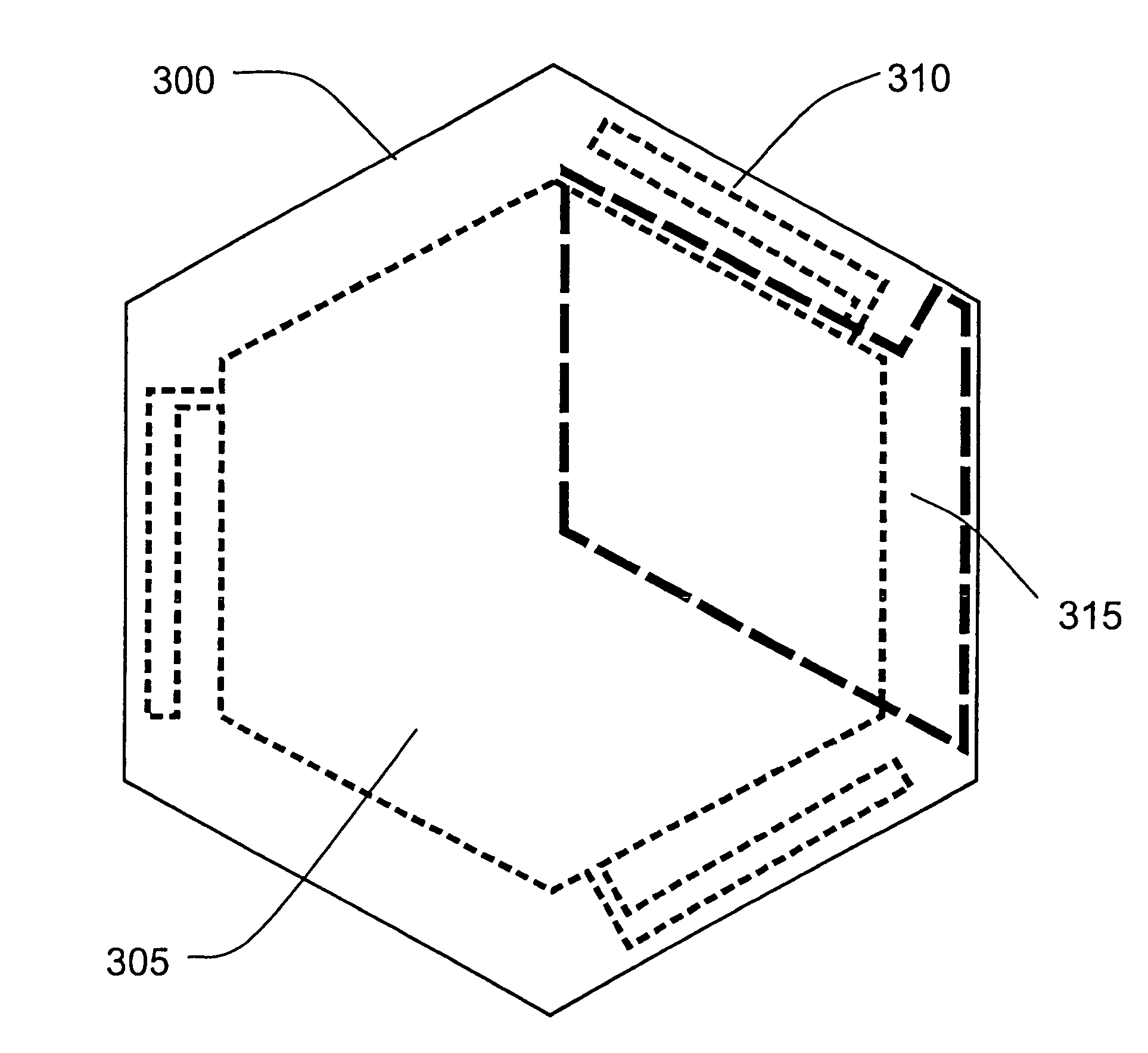
[0054]Another embodiment of the present invention minimizes the voltage necessary for actuation through the shaping of the actuation electrodes. For any actuator using electrostatic forcing, minimizing the voltage required for actuation is desirable as high voltage circuits are both expensive and complicated. From the equation governing electrostatic attraction between two parallel plate capacitors, those skilled in the art will recognize that for a fixed actuation force (Fe), decreasing the applied voltage (V) requires a decrease in the electrode gap (g), or an increase in the electrode area (A). Since the gap (g) is fixed by the stroke requi...
fourth embodiment
[0057]A fourth embodiment, shown in FIG. 9 of the present invention provides interconnect to the forcing electrodes of an actuator or an array of actuators. The invention allows interconnect lines to be routed beneath exposed forcing electrodes 315 while providing compatibility with the processing required for actuators. One or more interconnect lines made of polysilicon 905 are isolated from the substrate 320, other interconnect lines, and the actuator structure by silicon nitride layers 903 and 907. Each polysilicon electrical interconnect is encased in silicon nitride except at via locations 919 that allow electrical connection to polysilicon and actuator structural layers above.
[0058]In another embodiment, all four of the above embodiments above are combined to maximum benefit. Referring to FIG. 6, the anchoring to the substrate of the first set of flexures 601 and the attachment points 610 of the second set of flexures 609 attached to the intermediate frame 605 are rigid. Conve...
PUM
 Abstract
Description
Claims
Application Information
 - Generate Ideas
- Intellectual Property
- Life Sciences
- Materials
- Tech Scout
- Unparalleled Data Quality
- Higher Quality Content
- 60% Fewer Hallucinations
Browse by: Latest US Patents, China's latest patents, Technical Efficacy Thesaurus, Application Domain, Technology Topic, Popular Technical Reports.
© 2025 PatSnap. All rights reserved.Legal|Privacy policy|Modern Slavery Act Transparency Statement|Sitemap|About US| Contact US: help@patsnap.com


