
Air gas analyzer window and a method for producing such a window

a gas analyzer and air technology, applied in the field of air gas analyzer windows, can solve the problems of high cost of traditional gas windows, moisture deposits of adapters, and difficult production of traditional gas windows

Active Publication Date: 2009-12-08
PHASEIN
View PDF4 Cites 218 Cited by
  • Summary
  • Abstract
  • Description
  • Claims
  • Application Information

AI Technical Summary

Benefits of technology

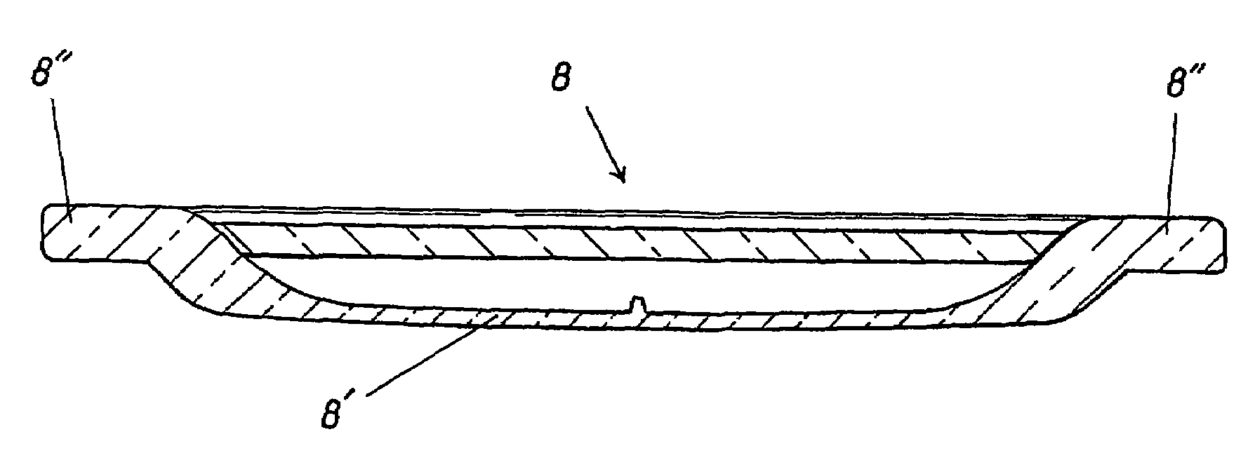
"The present invention provides a novel window for gas analysers that overcomes the problems and drawbacks associated with existing windows. The window is made of plastic material and has a round basic shape with a surrounding edge and a central part that forms the window through which IR rays shall pass. The central part of the window is arched away from the edge. The window can be fastened in the adapter by gluing, ultrasound welding or heat welding. The window design solution provides a window that can be injection molded with a thin section of sufficient thickness for optimal transmission properties. The method involves injecting plastic material into a mold and using a surface tension modifying substance or preheated mold tool."

Problems solved by technology

A particular problem that has been observed in respect of the aforesaid types of adapter resides in the moisture deposits that can occur on the inside of the adapter walls.
The windows through which the IR rays shall pass have been found to be a problematic source in those adapters of the aforesaid kind known hitherto.
The following problems have been observed among the various solutions proposed with regard to window designs:Traditional gas windows are expensive and often need to be heated in order to avoid moisture deposits.
Heating has the additional disadvantage of utilising power and also lengthens the time before which the sensor can begin to be used.
Heating also results in different material compositions that make recovery of the adapters used difficult to achieve.Foils that are sufficiently strong mechanically normally have a poor transmission capacity in high wavelength regions.
It has also been found difficult to flatten foil, therewith requiring some form of stretching or tensioning means, which, in turn, renders the elements twist responsive.
It is often also necessary to glue these additional fastener elements, in order to obtain a secure and tight fastening.The different component parts and the mounting steps involved make manufacture of the product expensive.
As mentioned above, the use of different materials also results in recovery problems.

Method used


Image

  • Air gas analyzer window and a method for producing such a window
  • Air gas analyzer window and a method for producing such a window
  • Air gas analyzer window and a method for producing such a window

Examples


Embodiment Construction

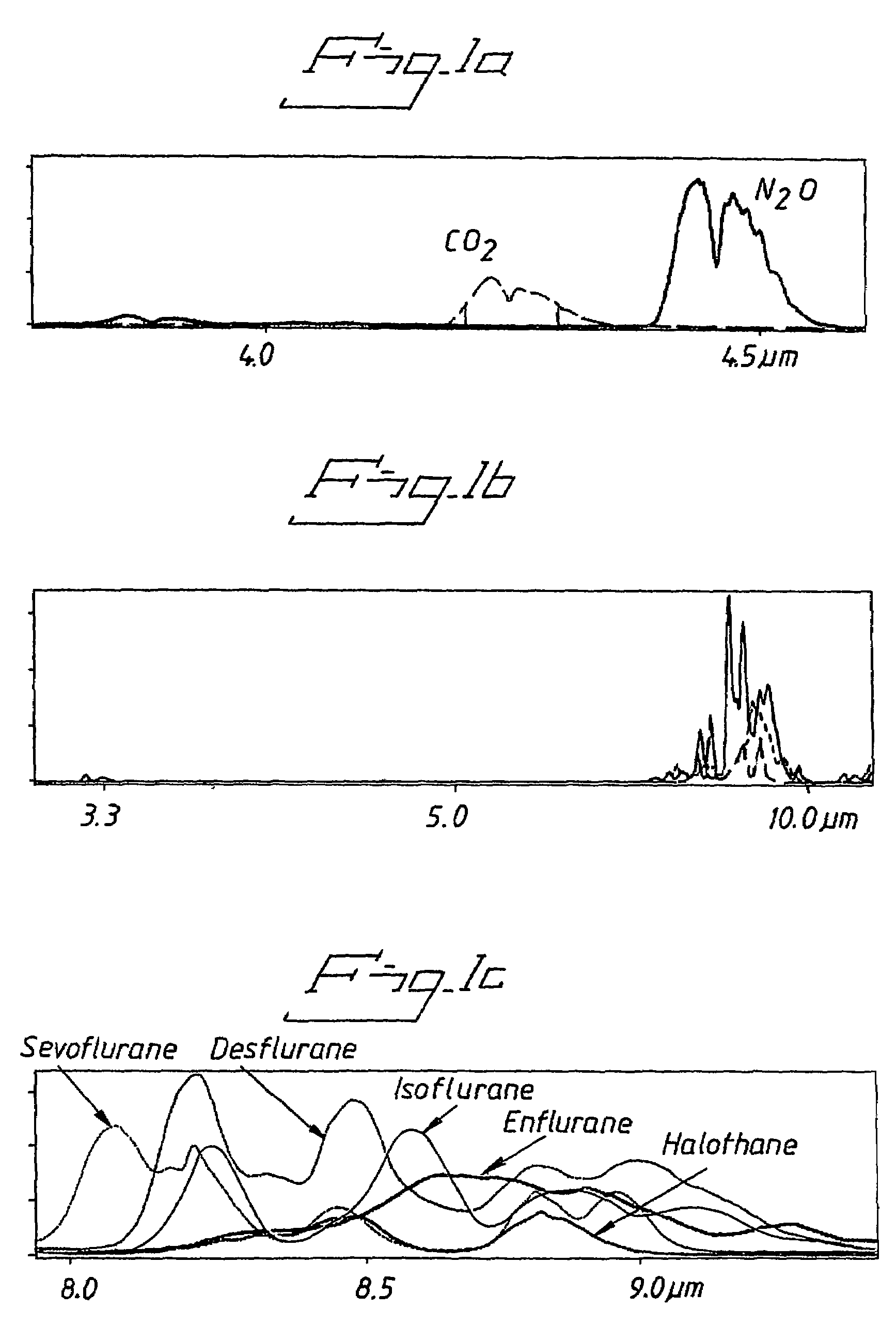
[0031]As before mentioned, FIG. 1 illustrates IR light absorption spectra in respect of the analysis of respiratory gases with the aid of an IR gas analyser. As will be seen from FIG. 1a, the absorption spectra of CO2 and N2O lie in the region of 4-4.5 μm, which is the region in which windows used hitherto exhibit good transmittance. In distinction, the windows used hitherto have poor transmittance in the region of 8-10 μm, which, as evident from FIG. 1b, is the region where the best absorption peaks for anaesthesia gases are found. FIG. 1c illustrates more specifically the absorption spectrum of the most common anaesthesia gases, from which it will be clearly seen that these absorption spectra are mainly found in the region of 8-9.5 μm. Accordingly, an object of the present invention has been the provision of a window which will provide good transmittance also at these wavelengths of the infrared light.

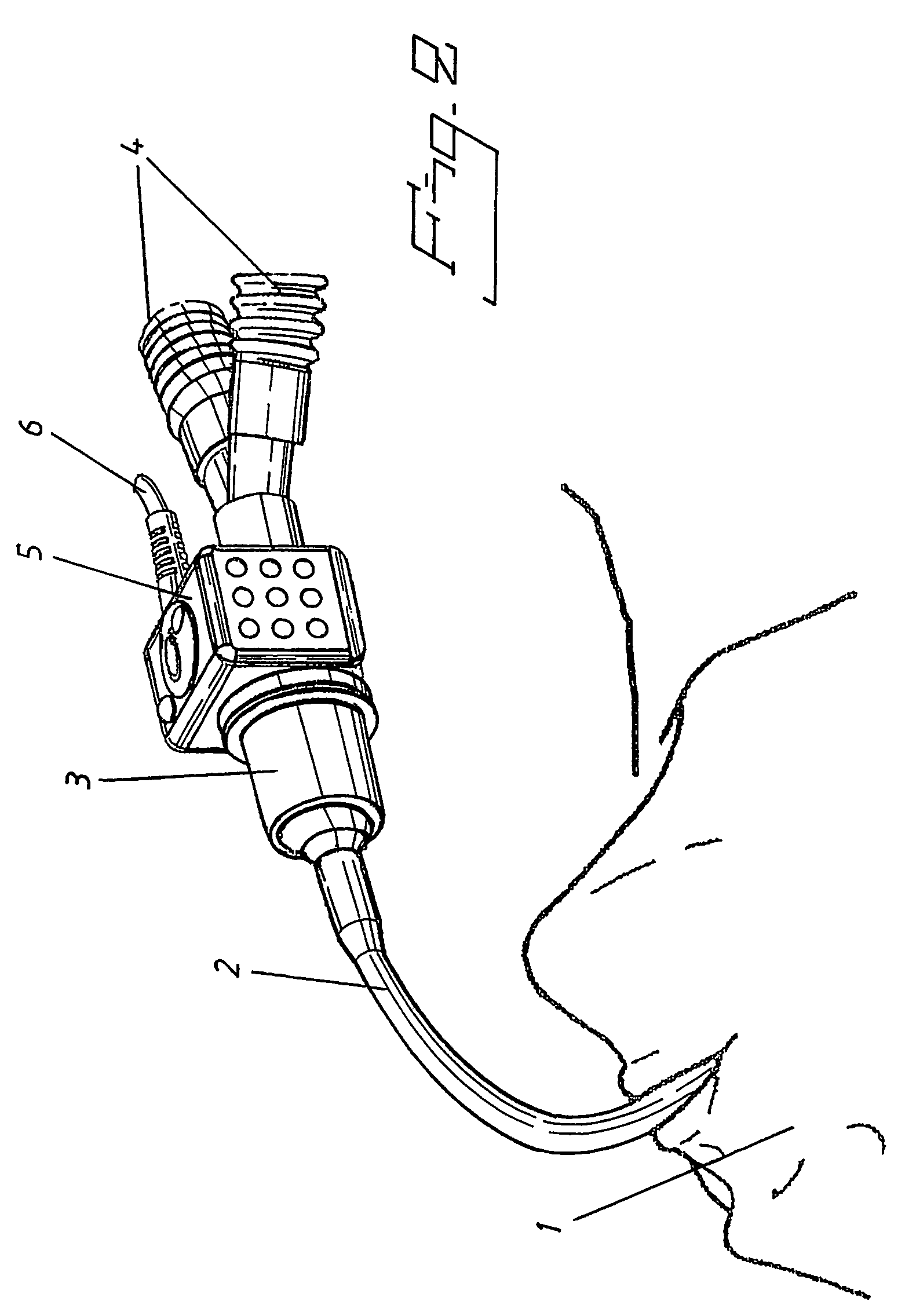
[0032]FIG. 2 illustrates the general principle of how respiratory gases to / from ...


PUM

PropertyMeasurementUnit
thicknessaaaaaaaaaa
thicknessaaaaaaaaaa
thicknessaaaaaaaaaa

Abstract

A window for use in an adapter for an IR gas analyser for analysing breathing gases, where the gases flow through a through-penetrating passageway in the adapter, which includes windows disposed on opposite sides of the passageway so as to enable an IR beam to be sent through the windows and through the passageway containing said breathing gases. Each window is a one-piece structure comprised of plastic material and has a round basic shape that includes a surrounding edge and a central part which is sunken in relation to the surrounding edge and which forms the window through which the IR beams or rays shall be able to pass. A method of producing such a window, by injection moulding a thermoplastic material in a mould where injection of the plastic material is also disclosed.

Description

BACKGROUND OF THE INVENTION[0001]1. Field of the Invention[0002]The present invention relates to an IR gas analyser window for particular use with an adapter of an IR gas analyser for the analysis of respiratory gases. The invention also relates to a particular method of producing such a window.[0003]2. Description of the Related Art[0004]Main flow measuring gas analysers calculate the composition of the respiratory gases of a patient, by sending infrared light through the respiratory tract of the patient and therewith measuring the absorption of said light at chosen wavelengths. For the sake of accuracy, main flow measuring gas analysers are placed as close as possible to the patient's mouth.[0005]In order to enhance the efficiency of such respiratory gas measuring processes, there has recently been adopted the use of adapters that are inserted in the respiratory circuit and through which the respiratory gases are allowed to pass, while, at the same time, coupling a measuring instr...

Claims


Application Information

Patent Timeline
Patent Type & Authority Patents(United States)
IPC IPC(8): B32B1/00A61B5/08B32B3/00B32B3/02A61B5/097B29C45/34G01N21/03G01N21/05G01N21/35
CPCA61B5/097B29C45/34G01N21/05G01N21/0303B29C2045/7356B29K2221/003Y10T428/24479G01N21/3504Y10T428/21Y10T428/24628Y10T428/31565
Inventor ECKERBOM, ANDERSZYZANSKI, ROBERT
Owner PHASEIN
Learn More