
Metallic container dome configured to deform at a predetermined pressure

a technology of metallic containers and domes, which is applied in the direction of domes, hollow objects, liquid dispensing, etc., can solve the problems of affecting the effectiveness of ingredients, the appearance, the fragrance, the appearance, and the color of products, and the pressure within the aerosol container may increase, so as to achieve economic effects of production

Active Publication Date: 2020-11-24
BALL METALPACK LLC
View PDF21 Cites 0 Cited by
  • Summary
  • Abstract
  • Description
  • Claims
  • Application Information

AI Technical Summary

Benefits of technology

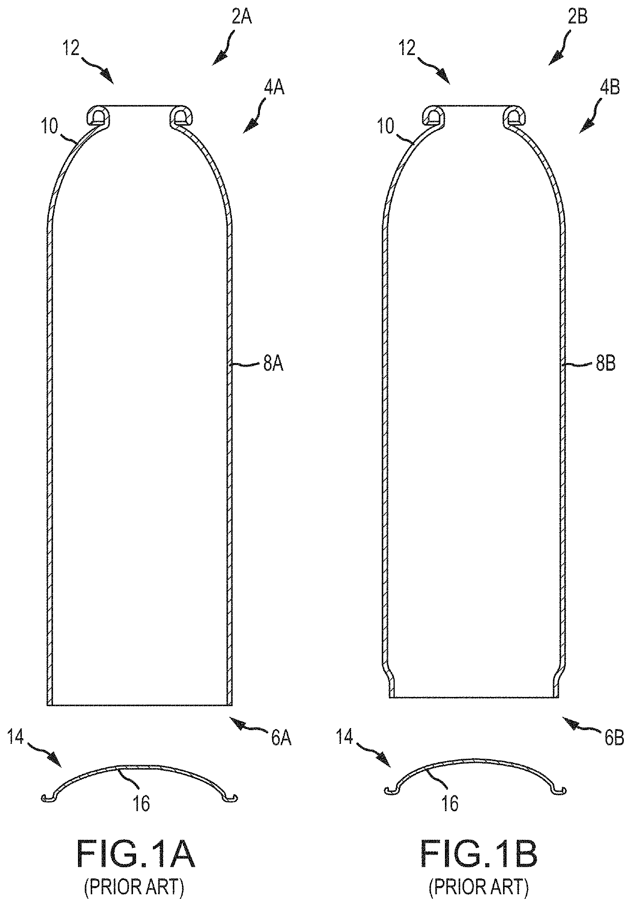
[0014]One aspect of the present invention is a metallic dome for a two-piece or a three-piece aerosol container. The metallic dome includes a flattened relief panel and an inwardly oriented arch having a geometry configured to buckle or deform outwardly when pressure within the aerosol container exceeds a predetermined amount. More specifically, the metallic dome is configured to deform such that the volume of an aerosol container to which the metallic dome is interconnected increases to prevent failure of the aerosol container, such as a rupture or seam separation. In one embodiment, the flattened relief panel is substantially centered on the metallic dome. The inwardly oriented arch may have a generally arcuate shape. In one embodiment, the inwardly oriented arch has a generally uniform radius of curvature. Alternatively, the metallic dome may be formed from two or more inwardly oriented arches with each arch having a different radius of curvature. In one embodiment, the metallic dome has a diameter selected to fit an aerosol container with a diameter of approximately 2 10 / 16 inches which is commonly known as a 210 container; however, the metallic dome may have a diameter selected to fit an aerosol container of any diameter.
[0016]In one embodiment, the inwardly oriented arch has a cross-sectional profile with a generally constant radius of curvature. Alternatively, the metallic dome may comprise two or more inwardly oriented arches, each arch having a different radius of curvature. In one embodiment, the metallic dome has four inwardly oriented arches each having a different radius of curvature. The flattened relief panel reduces the rigidity of the metallic dome. In one embodiment, the metallic dome of the present invention can withstand a pressure of up to at least approximately 225 psig without bursting or releasing a product. Additionally, in one embodiment, the metallic dome can withstand a pressure of up to approximately 275 psig without bursting or releasing a product. In one embodiment, the metallic dome is devoid of scores and coins. Optionally, no score or coins are formed on at least the flattened relief panel. In another embodiment, the metallic dome has a material thickness that is substantially uniform through the entire dome.
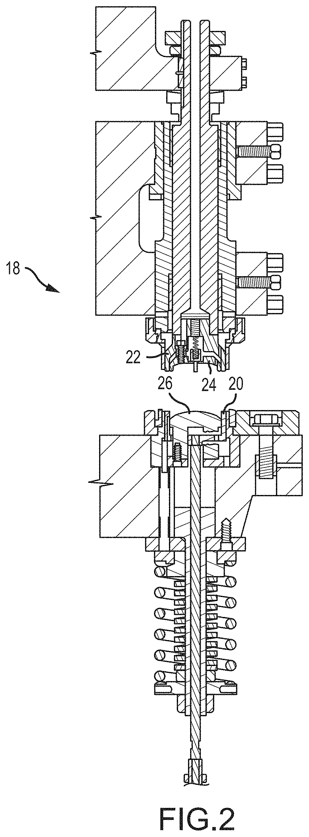
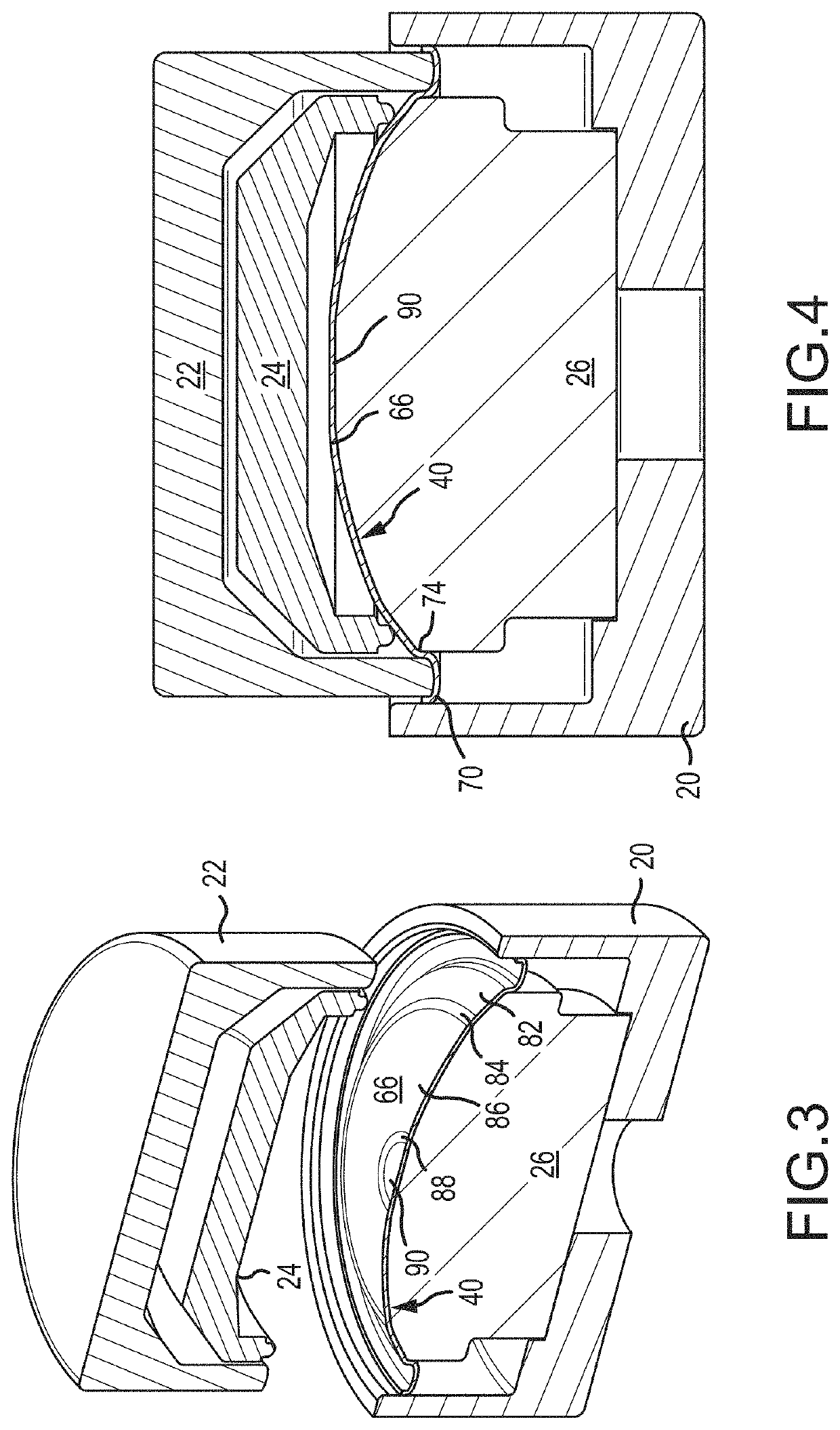
[0029]Another aspect of the present invention is a forming tool which is configured to replace a dome forming tool of a prior art tooling assembly. The forming tool has a face with a predetermined profile to produce a metallic dome for an aerosol container. The metallic dome has a geometry configured to deform in response to a predetermined pressure. In this manner, the tooling assembly may be modified to produce a metallic dome of the present invention by replacing only one tool of the tooling assembly with the forming tool of the present invention. Thus, the metallic dome of the present invention is economical to produce.

Problems solved by technology

For example, the metallic body prevents CO2 migration and UV radiation which may damage personal care, pharmaceutical, and food products and other UV-sensitive formulations, negatively influencing the effectiveness of ingredients, as well as the fragrance, flavor, appearance, or color of the product.
For example, when an aerosol container is left in sunlight or stored in a hot place for a period of time, the pressure within the aerosol container may increase due to thermal expansion of the product.
The increase in pressure can cause catastrophic failure when the container explodes.
These prior art pressure relief mechanisms have several deficiencies.
More specifically, some pressure relief mechanisms which are designed to increase the volume of the aerosol container do not perform consistently and predictably.
Instead, the pressure relief mechanism may roll-out or otherwise expand inconsistently or incompletely such that the volume of the aerosol container does not increase as intended.
Thus, pressure within the aerosol container does not decrease as expected or by a sufficient amount.
An uncontrolled failure of the aerosol container may thus occur resulting in spoilage or damage to other containers or products stored in the same packaging, vehicle, or storage area.
Pressure relief mechanisms with scores or notches may fail prematurely, or at an unnecessarily low pressure.
After the scores rupture, the aerosol container may have sharp edges which are particularly dangerous.
The scores are also known to corrode over time which may lead to failure of the aerosol container.
Pressure relief mechanisms that vent the contents of the aerosol container are also undesirable because the vented product may be dangerous or cause health concerns when inhaled or through contact with a person's skin or eyes.
This can cause problems when an aerosol container in an unventilated space, such as a warehouse or tractor-trailer, vents its contents through a pressure relief score.
Additionally, an aerosol container that ruptures or vents its contents can cause spoilage of other containers when the container product sprays onto other aerosol containers or packages.
As one of skill in the art will appreciate, the vented product may damage other containers or mar packaging and decorations making the other aerosol containers unsaleable.

Method used


Image

  • Metallic container dome configured to deform at a predetermined pressure
  • Metallic container dome configured to deform at a predetermined pressure
  • Metallic container dome configured to deform at a predetermined pressure

Examples


Embodiment Construction

[0064]The present invention has significant benefits across a broad spectrum of endeavors. It is the Applicant's intent that this specification and the claims appended hereto be accorded a breadth in keeping with the scope and spirit of the invention being disclosed despite what might appear to be limiting language imposed by the requirements of referring to the specific examples disclosed. To acquaint persons skilled in the pertinent arts most closely related to the present invention, a preferred embodiment that illustrates the best mode now contemplated for putting the invention into practice is described herein by, and with reference to, the annexed drawings that form a part of the specification. The exemplary embodiment is described in detail without attempting to describe all of the various forms and modifications in which the invention might be embodied. As such, the embodiments described herein are illustrative, and as will become apparent to those skilled in the arts, may be...


PUM

PropertyMeasurementUnit
pressureaaaaaaaaaa
pressureaaaaaaaaaa
pressureaaaaaaaaaa

Abstract

Methods and apparatus for forming a metallic dome are provided. More specifically, the present invention relates to a metallic dome that may be used to seal an aerosol container. The metallic dome includes a novel flattened relief panel and an inwardly oriented arch configured to deform in response to pressure within the aerosol container exceeding a predetermined amount. In one embodiment, the flattened relief panel is substantially planar. Optionally, the metallic dome includes at least a first inwardly oriented arch with a first radius of curvature and a second inwardly oriented arch with a second radius of curvature.

Description

CROSS-REFERENCE TO RELATED APPLICATIONS[0001]This application claims priority under 35 U.S.C. § 119(e) to U.S. Provisional Patent Application Ser. No. 62 / 507,462 filed May 17, 2017, which is incorporated herein by reference in its entirety.FIELD OF THE INVENTION[0002]The present invention relates generally to the manufacturing of metallic container bodies. More specifically, the present invention relates to methods and apparatus for forming a metallic dome for interconnection to a lower portion of a metallic container, the metallic dome including a pressure relief feature.BACKGROUND[0003]Metallic aerosol containers offer distributors and consumers many benefits. The metallic body of a container provides optimal protection properties for products. For example, the metallic body prevents CO2 migration and UV radiation which may damage personal care, pharmaceutical, and food products and other UV-sensitive formulations, negatively influencing the effectiveness of ingredients, as well a...

Claims


Application Information

Patent Timeline
Patent Type & Authority Patents(United States)
IPC IPC(8): B65D83/38B21D22/30B21D22/28B21D51/24
CPCB21D22/28B21D51/24B21D22/30B65D83/38
Inventor NESS, DAVID J.LORD, RICK L.
Owner BALL METALPACK LLC
Learn More