
Camera with image enhancement functions

a technology of image enhancement and camera, applied in the field of digital imaging, can solve the problems of blurred images captured by the array itself, high cost of defect-free detector arrays, exotic optical elements, etc., and achieve the effect of improving the image quality of digital imaging systems and high-quality images

Active Publication Date: 2009-12-01
DIGITALOPTICS CORPORATION
View PDF51 Cites 50 Cited by
  • Summary
  • Abstract
  • Description
  • Claims
  • Application Information

AI Technical Summary

Benefits of technology

[0007]Some embodiments of the present invention provide methods and devices for improving the image quality of digital imaging systems. These methods and devices are useful particularly in creating digital cameras with simple, low-cost lenses (or even no lenses) that produce high-quality images. The novel principles of optical design and image processing that are taught by the present invention, however, are also applicable to digital imaging systems of other types.
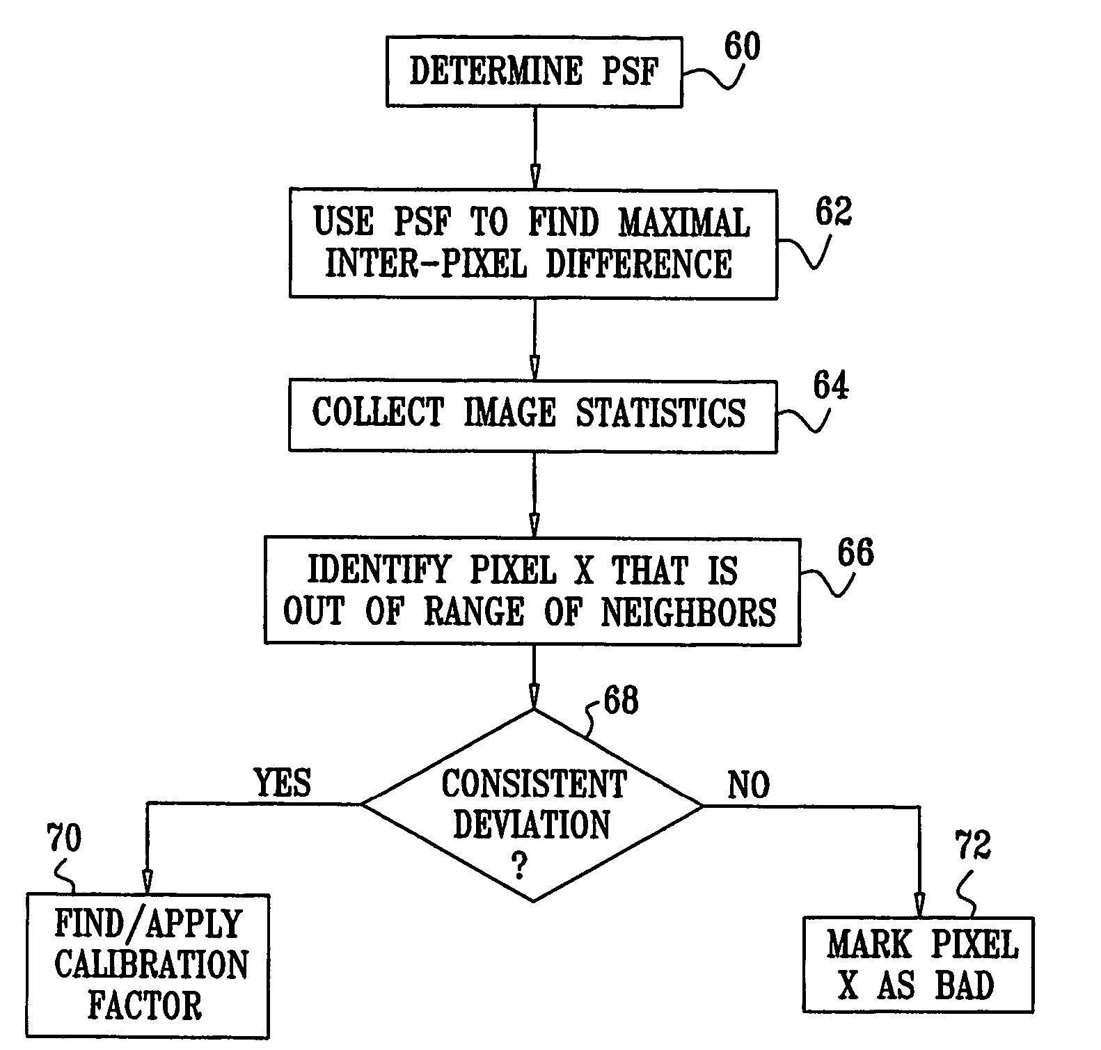
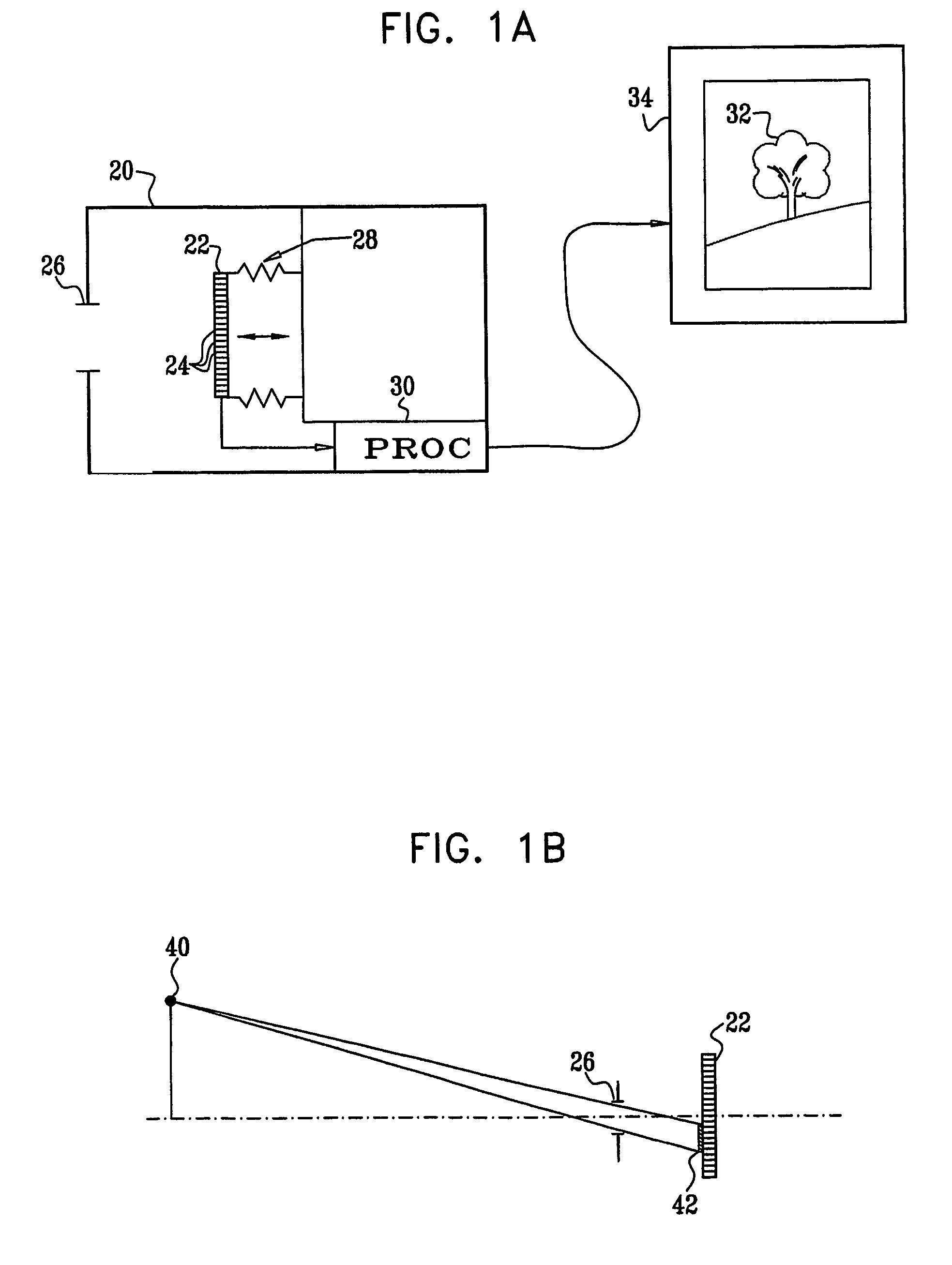
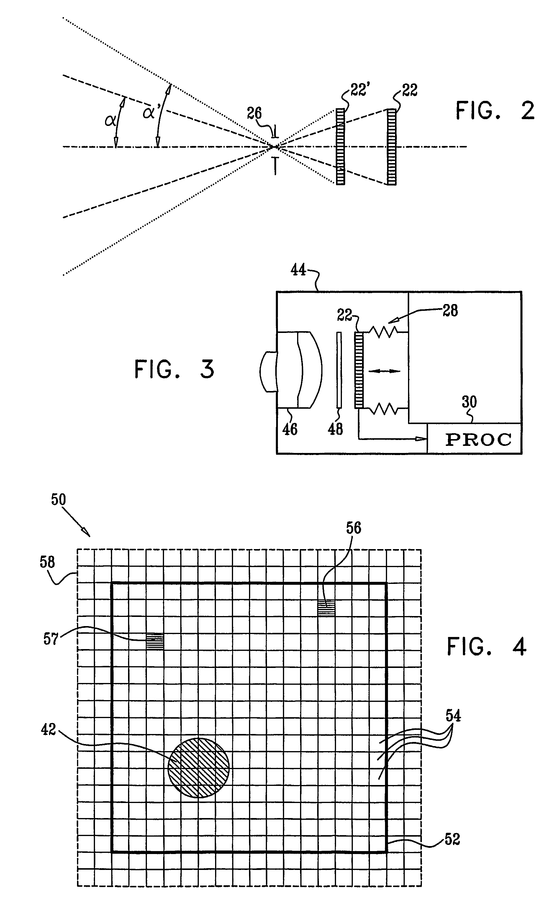
[0008]In some embodiments of the present invention, an electronic imaging camera comprises an image sensing array. The camera typically comprises objective optics, which image an object onto the array with a PSF of extent substantially greater than the pitch of the sensing array even at optimal focus of the optics. (In one embodiment, the “objective optics” simply comprise an aperture—in the nature of a large “pinhole”—with no lens at all.) As a result, the images captured by the array itself are blurred. An image processor, which may be integrated in the camera, applies a deblurring function—typically in the form of a deconvolution filter—to the signal output by the array in order to generate an output image with reduced blur. This blur reduction is made possible by novel methods of image processing described hereinbelow. These methods make it possible to design and use camera optics with a poor inherent PSF, while restoring the electronic image generated by the sensing array to give an acceptable output image.

Problems solved by technology

As a result, the images captured by the array itself are blurred.
Thus, these systems require exotic optical elements and are sensitive to variations in rotational alignment of the optics.
Because defect-free detector arrays are very costly, most electronic imaging cameras for consumer and industrial applications have a certain number of bad pixels, which do not produce a useful light signal.

Method used


Image

  • Camera with image enhancement functions
  • Camera with image enhancement functions
  • Camera with image enhancement functions

Examples


Embodiment Construction

[0073]The following is a non-exhaustive list of technical terms that are used in the present patent application and in the claims. Although these terms are used herein in accordance with the plain meaning accorded the terms in the art, they are listed below for the convenience of the reader in understanding the following description and the claims.[0074]Pitch of a detector array refers to the center-to-center distance between elements of the array.[0075]Cylindrical symmetry describes a structure, such as a simple or compound lens, which has an optical axis such that the structure is invariant under rotation about the optical axis for any and all angles of rotation.[0076]Point spread function (PSF), expressed herein as h, is the impulse response of an optical system in the spatial domain, i.e., the image formed by the system of a bright point object against a dark background.[0077]Extent of the PSF is the full width at half maximum (FWHM) of the PSF.[0078]Optical transfer function (O...


PUM


Abstract

Imaging apparatus (20, 44) includes an array (22) of optical sensing elements (24), characterized by a pitch, which is adapted to generate a signal in response to optical radiation that is incident on the elements. Objective optics (26, 46), which have an optical axis (134) and are characterized by a cylindrical symmetry about the axis, are arranged to focus the optical radiation from an object onto the array with a point spread function (PSF) having an extent greater than twice the pitch of the array at an optimal focus of the objective optics.

Description

CROSS-REFERENCE TO RELATED APPLICATIONS[0001]This application claims the benefit of U.S. Provisional Patent Application 60 / 440,561, filed Jan. 16, 2003. This application is related to U.S. patent application Ser. No. 09 / 778,849, filed Feb. 8, 2001, which was published as US 2002 / 0145671 A1. Both of these related applications are incorporated herein by reference.FIELD OF THE INVENTION[0002]The present invention relates generally to digital imaging, and specifically to methods and devices for enhancing image quality in digital cameras, as well as designing optics for such cameras.BACKGROUND OF THE INVENTION[0003]The inherent resolution of digital cameras known in the art, such as cameras based on CCD or CMOS sensor arrays, is generally limited by the resolution of the sensor array itself. In order to avoid degrading resolution still further, the objective optics used in such cameras are typically designed so that the optical point spread function (PSF) has an extent smaller than the p...

Claims


Application Information

Patent Timeline
Patent Type & Authority Patents(United States)
IPC IPC(8): G06K9/40G02B13/16G03B13/00H04N5/225H04N5/232H04N5/262G02B27/00G02B27/58G06T5/00H04N5/367
CPCG02B27/0012G02B27/0025H04N5/367G06T5/003G06T5/005H04N5/3675G06T2207/30168H04N25/683H04N25/68G06T5/00G06T1/00H04N5/208H04N23/00
Inventor ALON, ALEXALON, IRINA
Owner DIGITALOPTICS CORPORATION
Learn More