Stator component for an electric motor

a technology of electric motors and components, which is applied in the direction of magnetic circuit rotating parts, dynamo-electric machines, magnetic circuit shape/form/construction, etc., can solve the problems of increasing the operating frequency of the motor, increasing the heat generation the loss of the magnetic core, and the manufacturing process is limited in the variation of the design of the sheet metal core. , to achieve the effect of reducing manufacturing costs, reducing yoke saturation, and optimizing the pole shap

Inactive Publication Date: 2009-12-01
MINEBEAMITSUMI INC
View PDF7 Cites 4 Cited by
  • Summary
  • Abstract
  • Description
  • Claims
  • Application Information

AI Technical Summary

Benefits of technology

[0007]It is an object of the present invention to provide a stator component of a motor. The stator component should be designed so as to reduce manufacturing costs, to optimize pole shape, to reduce yoke saturation, and to minimize core losses to improve the overall efficiency of the motor.
[0010]Preferably, the stator component is manufactured by the metal powder metallurgy method. The stator component consists of a ferromagnetic metal powder and an insulating binder added to the metal powder. The ferromagnetic metal powder preferably is a powder primarily comprising iron or nickel or a mixture thereof. Compared to a stator made of sheet metal, the metal powder stator component has less core loss in high frequencies due to high specific resistance. A major advantage of a metal powder stator component is that it can be freely designed in any desired construction shape.
[0018]In order to support and / or guide the coil wire, channels or slots are formed in the surface of the stator yoke. Each channel or slot has two openings, wherein one opening lies adjacent to the neck of one pole and the other opening lies adjacent to the neck of a neighboring pole. This facilitates the crossover of the coil wire from one pole to the other pole.

Problems solved by technology

Although a sheet metal stator core has advantages of high saturation magnetic flux density and relative inexpensiveness, there has been a problem in that eddy current in the metal plates increases rapidly with increase in operating frequency of the motor.
As a result of this, heat generation in the sheet metal core and magnetic core loss increase rapidly.
It is a further drawback that variations to the design of the sheet metal cores are limited by the manufacturing process.

Method used


Image

  • Stator component for an electric motor
  • Stator component for an electric motor
  • Stator component for an electric motor

Examples


Embodiment Construction

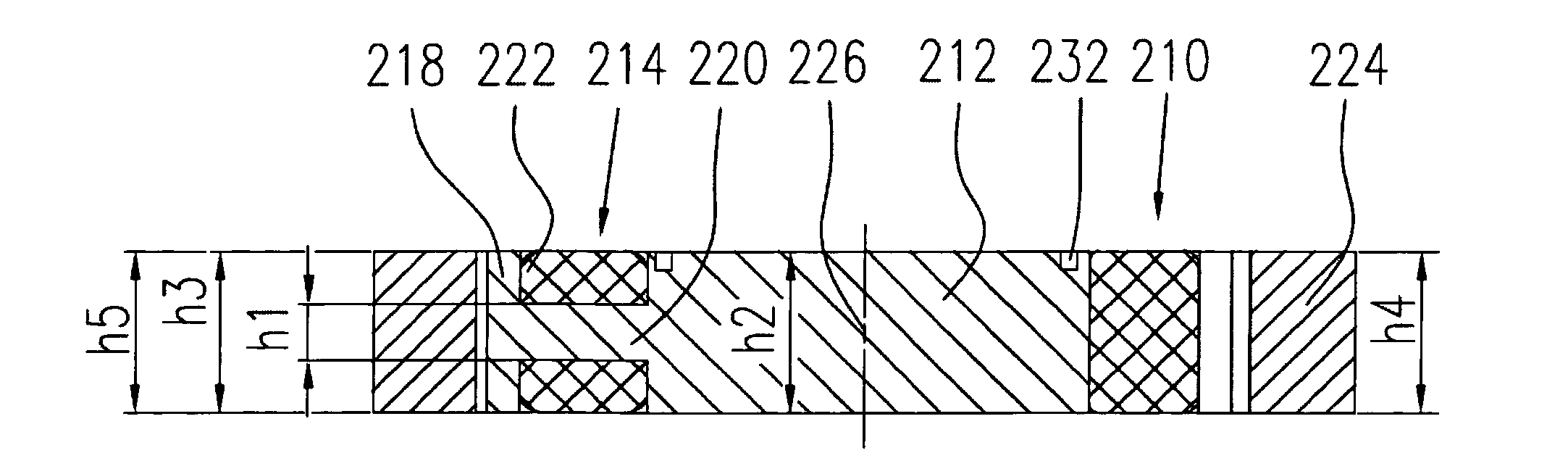
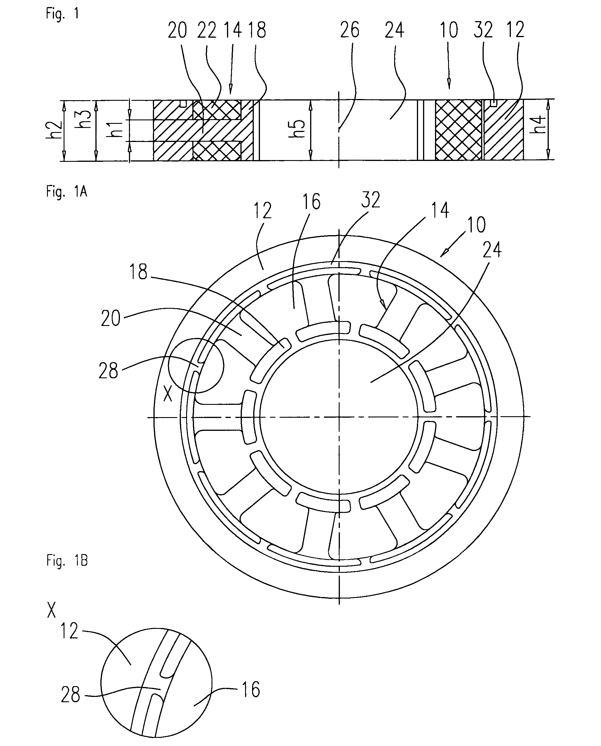
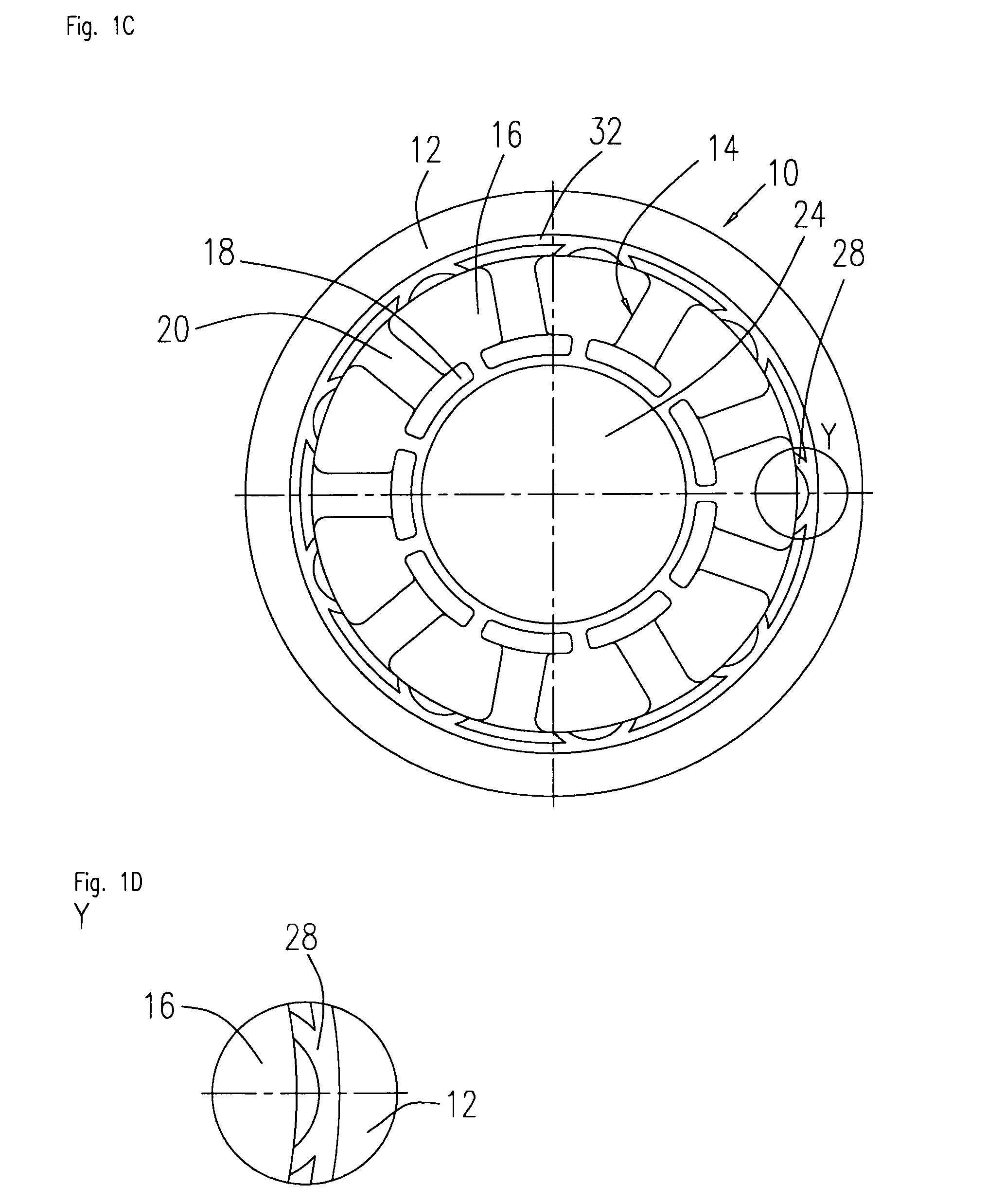
[0033]FIGS. 1 and 1A show a schematic cross section and a top view of a stator component 10 for use in an internal rotor electrical motor, particularly an electronically-commutated direct current motor.

[0034]The stator component 10 consists of a ring-shaped coil flux guide or yoke 12 having a height h2 and supporting several stator poles 14. In the present example nine stator poles 14 are shown. The stator poles 14 are spaced apart from each other and are regularly arranged along the inner periphery of the stator yoke 12. Each pole 14 extends radially inward from the inner periphery of the stator yoke 12. Stator slots 16 are formed between the poles 14.

[0035]Each pole 14 consists of a pole shoe 18 having a height h3 and a neck 20 having a height h1. The neck 20 connects the pole shoe 18 to the inner periphery of the stator yoke 12. A coil 22, which is part of a phase winding, is wound around each neck 20. The coil has a height h4. At a number of nine poles, three poles 18 are availa...


PUM


Abstract

The present invention relates to a stator component for an electric motor. The stator component for an internal rotor motor comprises a circular stator yoke having an inner periphery, a number of poles, the poles spaced apart from each other along the inner periphery of the stator yoke and extending radially inward from the inner periphery of the stator yoke, wherein each pole consists of an enlarged pole shoe and a neck connecting the pole shoe to the stator yoke, whereinthe axial height of the stator yoke is higher than the axial height of the neck of each pole, and a coil wound around the neck of each pole.The invention also relates to a stator component for an external rotor motor, wherein the stator poles are arranged along an outer periphery of the stator yoke and extending radially outward from the outer periphery of the yoke.

Description

FIELD OF THE INVENTION[0001]It is described a stator component for an electric motor, the stator component comprising of a ring-shaped stator yoke with enlarged pole shoes and a routing wire channel.BACKGROUND OF THE INVENTION[0002]The invention is generally related to electric motors, particularly electronically-commutated, brushless direct current (BLDC) motors. Motors of this kind can be used in a variety of applications, examples being in automotive engineering for fans, cooling pumps or steering system support. Other application areas include ventilator fans in power supply units, or spindle motors in disk drives for data processing systems, just to mention a few.[0003]A brushless DC motor basically consists of a shaft, a rotor assembly equipped with one or more permanent magnets arranged on the shaft, and a stator assembly which incorporates a stator component and phase windings. Bearings are mounted at an axial distance to each other on the shaft to support the rotor assembly...

Claims


Application Information

Patent Timeline
Patent Type & Authority Patents(United States)
IPC IPC(8): H02K1/00
CPCH02K1/02H02K1/30H02K1/146
Inventor GU, CHUNHUI
Owner MINEBEAMITSUMI INC
Why Eureka
Try Eureka