Mass magnifier using magnetic fields and mu-metal to provide an energy storage flywheel for use in conventional, microtechnology, and nanotechnology engines

a technology of magnetic fields and magnetic materials, applied in the direction of magnets, mechanical energy handling, magnetic bodies, etc., can solve the problem of inability to supply more than minute quantities of energy

Inactive Publication Date: 2009-12-01
BRIDGEWAY RES
View PDF8 Cites 8 Cited by
  • Summary
  • Abstract
  • Description
  • Claims
  • Application Information

AI Technical Summary

Problems solved by technology

One of the drawbacks currently in nano-technology components is the ability to supply more than minute quantities of energy at one time.

Method used


Image

  • Mass magnifier using magnetic fields and mu-metal to provide an energy storage flywheel for use in conventional, microtechnology, and nanotechnology engines
  • Mass magnifier using magnetic fields and mu-metal to provide an energy storage flywheel for use in conventional, microtechnology, and nanotechnology engines
  • Mass magnifier using magnetic fields and mu-metal to provide an energy storage flywheel for use in conventional, microtechnology, and nanotechnology engines

Examples


Embodiment Construction

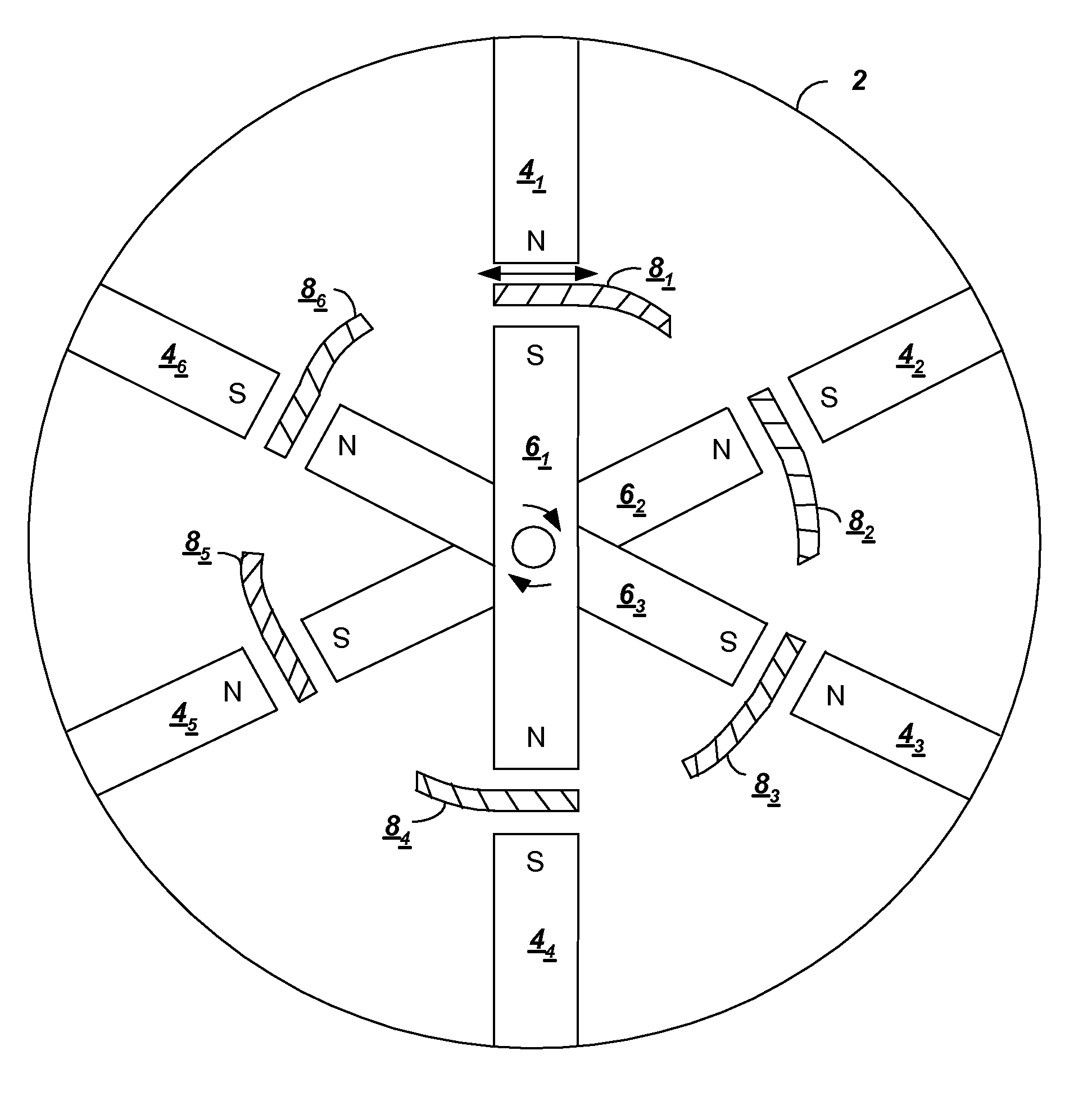
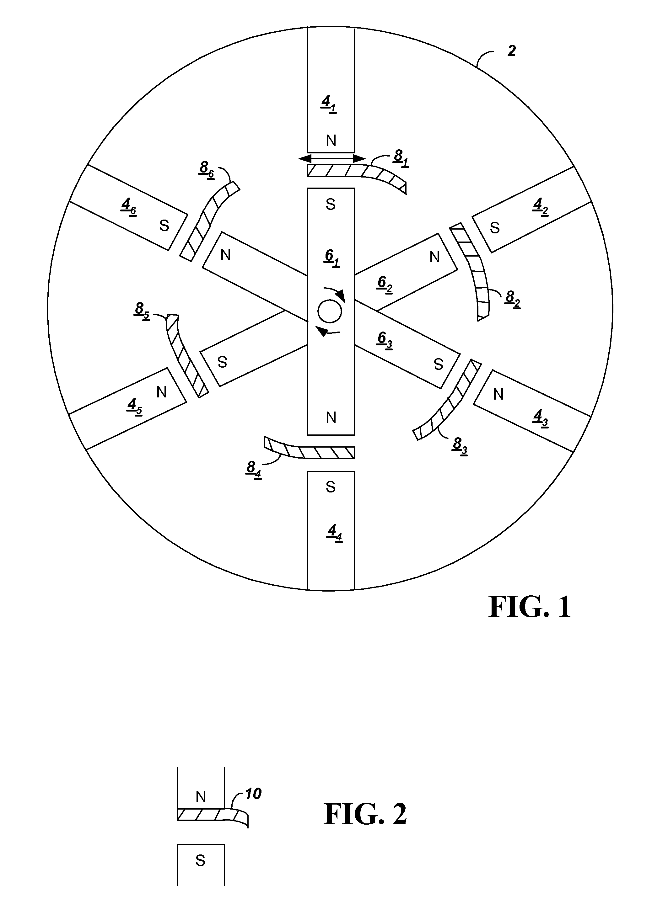
[0021]FIG. 1 shows a cross sectional view illustrating components of a mass magnifier according to one embodiment of the present invention. The mass magnifier includes a cylinder or drum 2 with magnetic devices 41-6 placed around the circumference of the cylinder 2. The magnetic devices 41-6 can be permanent magnets or electromagnets, as can other components described as magnetic devices herein. The cylinder 2 and magnetic devices 41-6 in the embodiment shown are assumed to be fixed in place to form a stator. Additional two pole magnets 61-3 are rotatably connected together inside the cylinder 2 to form a rotor. Rotation of the rotor is illustrated by the arrows going in a clockwise direction, although rotation can likewise be counterclockwise. Although rotation of the center magnetic devices 41-6 is illustrated, a further embodiment of the present invention allows for rotation of the cylinder 2 with magnets 41-6, while magnets 61-3 remain fixed.

[0022]Between the stator magnets 41-6...


PUM


Abstract

A mass magnifier is created by combining the properties of permanent magnets or electromagnets with the property of mu-metal to create a novel energy storage device. In a system mu-metal is placed in the magnetic field created by a magnet or electromagnetic in a manner to provide an energy storage device, similar to a fly wheel. The system includes a set of magnets arranged in a circle around a cylinder in a stationary position, effectively forming a stator. Another set of opposing magnets are arranged to form a rotor. When the rotor is rotated, mu-metal material is inserted between the rotor and stator magnets in a manner so that the rotor will remain in motion in a desired rotation direction, even if an opposing force is applied to the rotor axle. The system, thus, forms an energy storage device similar to a fly wheel. The system can also provide energy storage for conventional machines or for smaller micro-technology or nano-technology type devices.

Description

BACKGROUND[0001]1. Technical Field[0002]The present invention relates energy storage devices using magnetic fields and a material, such as mu-metal, that can provide the property of screening or attenuating magnetic fields. More particularly, the present invention relates to components used in constructing an energy storage device, such as a fly wheel, using magnetic fields and mu-metal.[0003]2. Related Art[0004]Magnetic fields can be created by permanent magnets or electro magnets. The magnetic field generated can be used to create magnets to lift metal containers or scrap metal, to deflect charged particles as in a cathode ray tube, and to operate electric motors. Many uses for magnetic fields have been discovered, and it would be desirable to provide a means to enhance those uses or enable potentially untapped uses for magnetic fields.[0005]Control of the electro magnetic field enables components such as magnetic lifting devices, charged particle deflectors, or electric motors to...

Claims


Application Information

Patent Timeline
Patent Type & Authority Patents(United States)
IPC IPC(8): H02K49/00H02P15/00
CPCH02K7/025Y02E60/16
Inventor BROWN, FORREST J.
Owner BRIDGEWAY RES
Why Eureka
Try Eureka