
Infrared sensor

a technology of infrared sensor and infrared light, which is applied in the field of infrared light sensor, can solve the problem that the infrared light sensor cannot provide maximum efficiency and viewing angle, and achieve excellent electromagnetic-wave resistance characteristics and high electromagnetic shielding characteristics

Active Publication Date: 2009-12-01
MURATA MFG CO LTD
View PDF11 Cites 1 Cited by
  • Summary
  • Abstract
  • Description
  • Claims
  • Application Information

AI Technical Summary

Benefits of technology

[0009]In order to solve the problems described above, preferred embodiments of the present invention provide a small infrared sensor that can provide a wide infrared light-receiving area (viewing angle), and an infrared sensor having high electromagnetic shielding characteristics and excellent electromagnetic-wave resistance characteristics.
[0014]The infrared sensor preferably includes an infrared sensor element, a box package, which accommodates the infrared sensor element in the interior thereof, and an optical filter, which is disposed so as to cover the opening of the package and functioning simultaneously as a filter and a cover that seals the opening. In the infrared sensor, supporting portions are disposed at four corners of the opening, whose shape is substantially rectangular in plan view, of the package. In addition, the supporting portions support the optical filter, which is disposed so as to cover the opening, at positions that are lower than the upper end of the inner peripheral wall defining the opening. While the optical filter is supported by the supporting portions as a result of inserting a portion of a surface side of the optical filter facing the supporting portions into the opening, the optical filter is secured to the package. Therefore, a proportion of a portion (area) that blocks a viewing angle to an entire surface area of the optical filter can be considerably reduced. Therefore, practically speaking, it is possible to mount the optical filter to the package without narrowing an infrared light-receiving area (viewing angle).
[0015]Since supporting portions are provided at the four corners of the opening whose shape is substantially rectangular in plan view, the optical filter is reliably held, so that it is possible to provide a highly reliable infrared sensor.
[0016]When the optical filter and the package are joined and secured to each other through a conductive adhesive, electrical connection and mechanically joining and securing of the optical filter and the package to each other can be simultaneously and more reliably performed. Therefore, preferred embodiments of the present invention can be made more effective.
[0017]The package preferably includes a metallic package body and an insulating covering material that covers a main portion of the metallic package body. The metallic package body is exposed at an area that is connected to the optical filter through the conductive adhesive, so that the conductive adhesive electrically connects the optical filter and the package body to each other. In this case, it is possible to reliably provide a highly reliable ceramic electronic component having the optical filter and the package electrically connected to each other while being insulated from the outside, so as to provide excellent electromagnetic shielding characteristics and insulation characteristics with respect to the outside. Therefore, preferred embodiments of the present invention can be made even more effective.

Problems solved by technology

Therefore, the infrared sensor cannot provide a viewing angle with maximum efficiency.

Method used


Image

  • Infrared sensor
  • Infrared sensor
  • Infrared sensor

Examples


Embodiment Construction

[0030]Features of the present invention will be described below in more detail with reference to preferred embodiments of the invention.

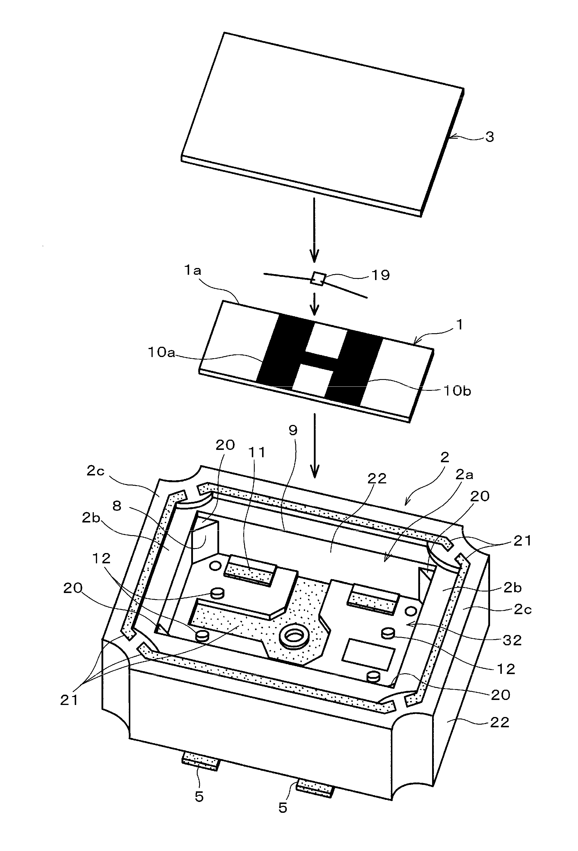
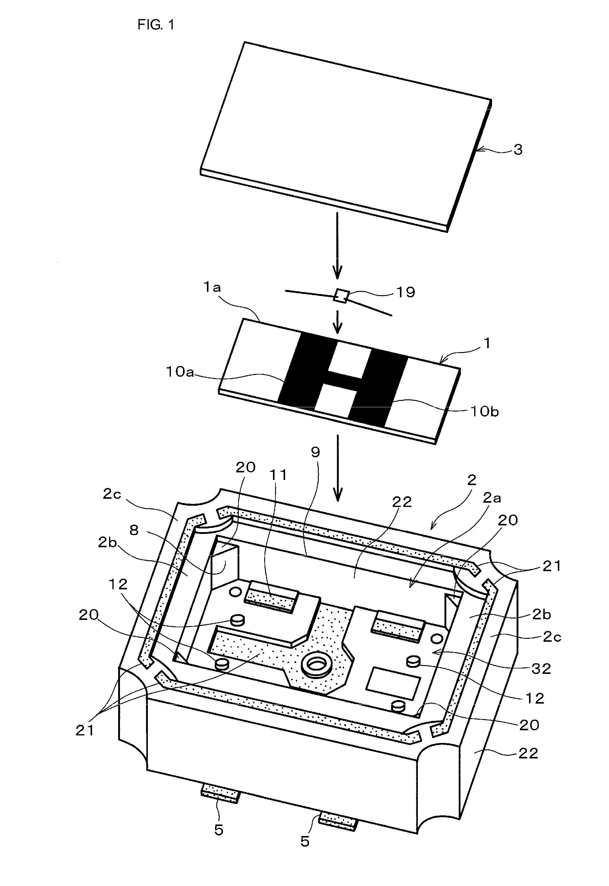
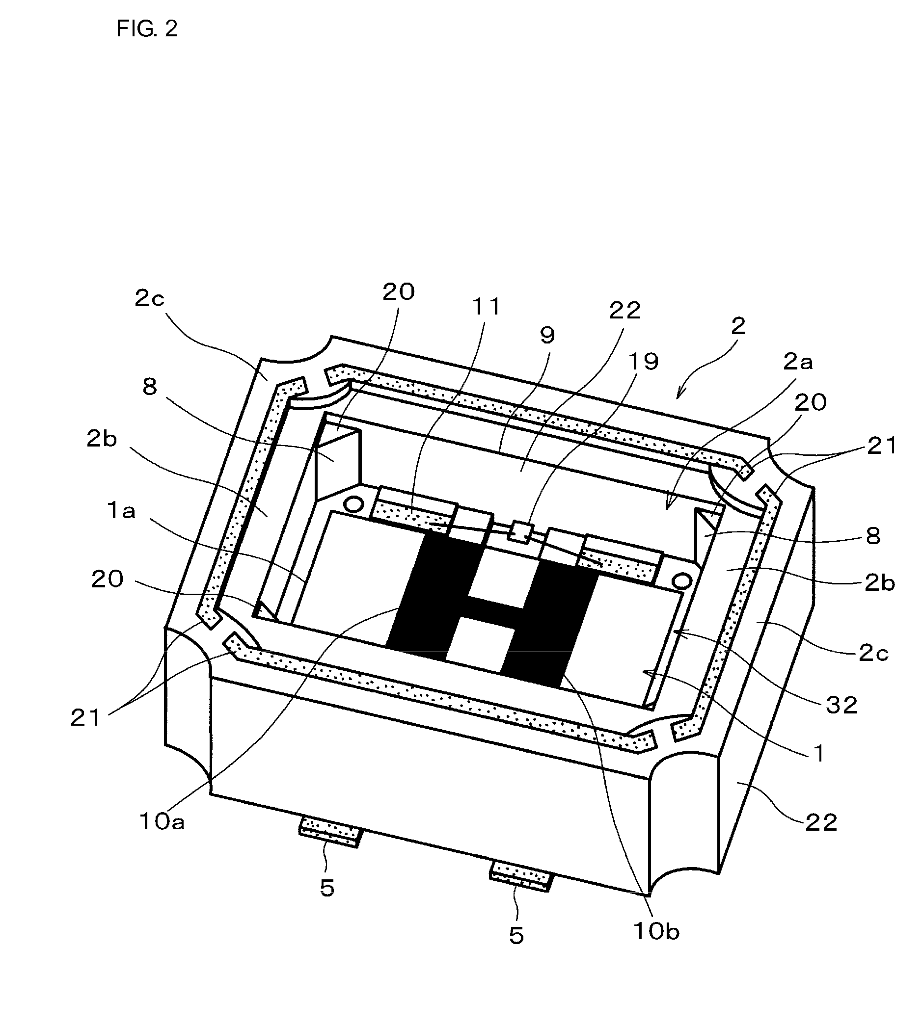
[0031]FIG. 1 is an exploded perspective view of an infrared sensor according to a preferred embodiment of the present invention. FIG. 2 shows a state in which an infrared sensor element is accommodated. FIG. 3 is a perspective view showing a state in which an optical filter is mounted to an opening of a package. FIG. 4 is an enlarged view of a main portion of cross section taken along line I-I of the infrared sensor shown in FIG. 3. FIG. 5 is an enlarged view of a main portion of a cross section taken along line II-II shown in FIG. 3.

[0032]The infrared sensor includes an infrared sensor element 1, a metallic package 2, and an optical filter 3. The package 2 has a box shape and has one side (top side in FIG. 1) open. In addition, the package 2 has electrodes 11 (and wiring patterns, etc.) provided in its interior portion. Further, the package 2 accom...


PUM


Abstract

A small infrared sensor has a wide infrared light-receiving area (viewing angle), high electromagnetic shielding characteristics, and excellent electromagnetic-wave resistance characteristics. In the infrared sensor, supporting portions are disposed at four corners of a substantially rectangular opening in a package. The supporting portions support an optical filter, disposed so as to cover the opening, at positions that are lower than an upper end of an inner peripheral wall defining the opening. While the optical filter is supported by the supporting portions as a result of inserting a portion of a surface side of the optical filter facing the supporting portions into the opening, the optical filter is secured to the package. The optical filter and the package are joined and secured, and electrically connected to each other through a conductive adhesive.

Description

BACKGROUND OF THE INVENTION[0001]1. Field of the Invention[0002]The present invention of the application relates to an infrared sensor. More particularly, the present invention relates to an infrared sensor having a wide viewing angle and detecting infrared radiation, and to an infrared sensor having improved electromagnetic shielding characteristics.[0003]2. Description of the Related Art[0004]As one type of related infrared sensor used in, for example, human body detection and crime-preventing devices, the following infrared sensor with lead terminals is provided. As shown in FIG. 6, in the infrared sensor, an infrared sensor element 53 having light-receiving electrodes 61 disposed on a pyroelectric element 62 is supported on a metallic base (stem) 52 having lead terminals 51. In addition, the infrared sensor element 53 is accommodated in a cylindrical metallic case (cap) 55 including an optical filter 54 provided at the upper surface side of the case 55 and transmitting infrared ...

Claims


Application Information

Patent Timeline
Patent Type & Authority Patents(United States)
IPC IPC(8): G01J5/02
CPCG01J1/0407G01J1/04G01J1/0271G01J2001/0276
Inventor HAYASHI, KOJITAKEDA, TAKESHI
Owner MURATA MFG CO LTD
Learn More