
Stimulus regimens for cardiovascular reflex control

a stimulus and cardiovascular technology, applied in the field of medical devices, can solve the problems of increased blood pressure, heart failure and stroke, and heart must work harder to maintain blood flow at the higher pressur

Inactive Publication Date: 2009-11-24
CVRX
View PDF213 Cites 147 Cited by
  • Summary
  • Abstract
  • Description
  • Claims
  • Application Information

AI Technical Summary

Benefits of technology

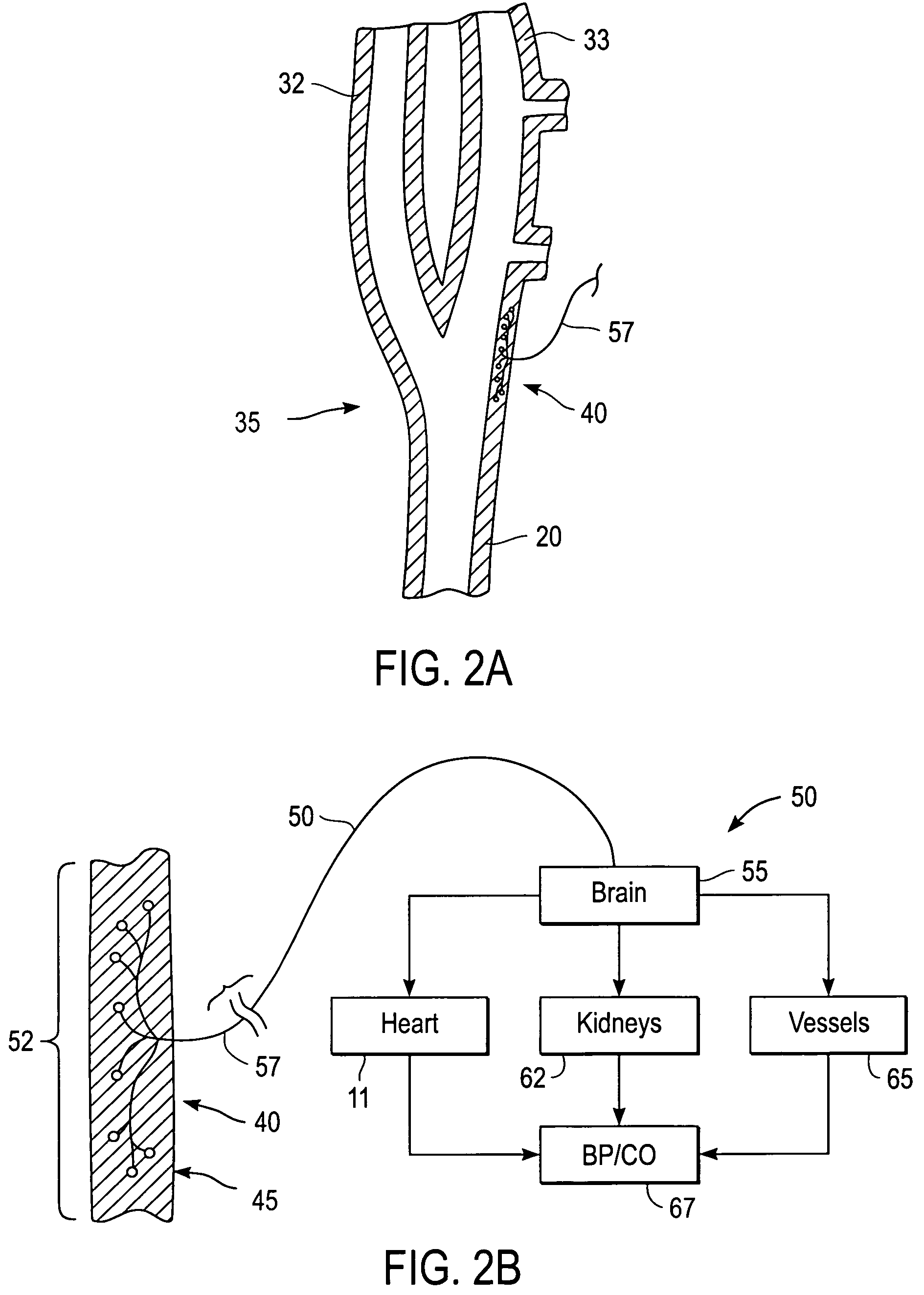
[0017]In general, cardiovascular receptors may be sensitive to pressure and / or mechanical deformation and are referred to as baroreceptors, mechanoreceptors, pressoreceptors, stretch receptors, and the like. For cardiovascular and renal therapies, the present invention is intended to activate or otherwise interact with any or all of these types of receptors and / or nerve fibers from the receptors so long as such activation or interaction results in modulation of the reflex control of the patient's circulation. While there may be small structural or anatomical differences among various receptors in the vasculature, for the purposes of the present invention, activation may be directed at any of these receptors and / or nerves from these receptors so long as they provide the desired effects. In particular, such receptors will provide afferent signals, i.e., signals to the brain, which provide the blood pressure and / or volume information to the brain. This allows the brain to cause “reflex” changes in the autonomic nervous system, which in turn modulate organ activity to maintain desired hemodynamics and organ perfusion. For convenience, the term “baroreceptor” will be used to refer to any or all of such receptors.

Problems solved by technology

Hypertension, or high blood pressure, is a major cardiovascular disorder that is estimated to affect over 50 million people in the United Sates alone, and is a leading cause of heart failure and stroke.
Hypertension occurs in part when the body's smaller blood vessels (arterioles) constrict, causing an increase in blood pressure.
Because the blood vessels constrict, the heart must work harder to maintain blood flow at the higher pressures.
Sustained hypertension may eventually result in damage to multiple body organs, including the kidneys, brain, eyes and other tissues, causing a variety of maladies associated therewith.
The elevated blood pressure may also damage the lining of the blood vessels, accelerating the process of atherosclerosis and increasing the likelihood that a blood clot may develop.
This could lead to a heart attack and / or stroke.
Sustained high blood pressure may eventually result in an enlarged and damaged heart (hypertrophy), which may lead to heart failure.
It is characterized by an inability of the heart to pump enough blood to meet the body's needs and results in fatigue, reduced exercise capacity and poor survival.
Although each of these alternative approaches is beneficial in some ways, each of the therapies has its own disadvantages.
For example, drug therapy is often incompletely effective.
Drugs often have unwanted side effects and may need to be given in complex regimens.
These and other factors contribute to poor patient compliance with medical therapy.
Drug therapy may also be expensive, adding to the health care costs associated with these disorders.
Likewise, surgical approaches are very costly, may be associated with significant patient morbidity and mortality and may not alter the natural history of the disease.
Baropacing also has not gained acceptance.
These include the invasiveness of the surgical procedure to implant the nerve electrodes, and postoperative pain in the jaw, throat, face and head during stimulation.
In addition, it has been noted that high voltages sometimes required for nerve stimulation may damage the carotid sinus nerves.

Method used


Image

  • Stimulus regimens for cardiovascular reflex control
  • Stimulus regimens for cardiovascular reflex control
  • Stimulus regimens for cardiovascular reflex control

Examples


Embodiment Construction

[0043]The following detailed description should be read with reference to the drawings in which similar elements in different drawings are numbered the same. The drawings, which are not necessarily to scale, depict illustrative embodiments and are not intended to limit the scope of the invention. The drawings illustrate the specific embodiment where one or more baroreflex activation devices are positioned near baroreceptors, but the invention is applicable to baroreflex activation devices that are positioned near nerve fibers that carry signals from the baroreceptor to the brain.

Anatomical Overview

[0044]To better understand the present invention, it may be useful to explain some of the basic vascular anatomy associated with the cardiovascular system. FIG. 1 is a schematic illustration of the chest and head regions of a human body 10 showing some of the major arteries and veins of the cardiovascular system. The left ventricle of the heart 12 pumps oxygenated blood up into the aortic ...


PUM


Abstract

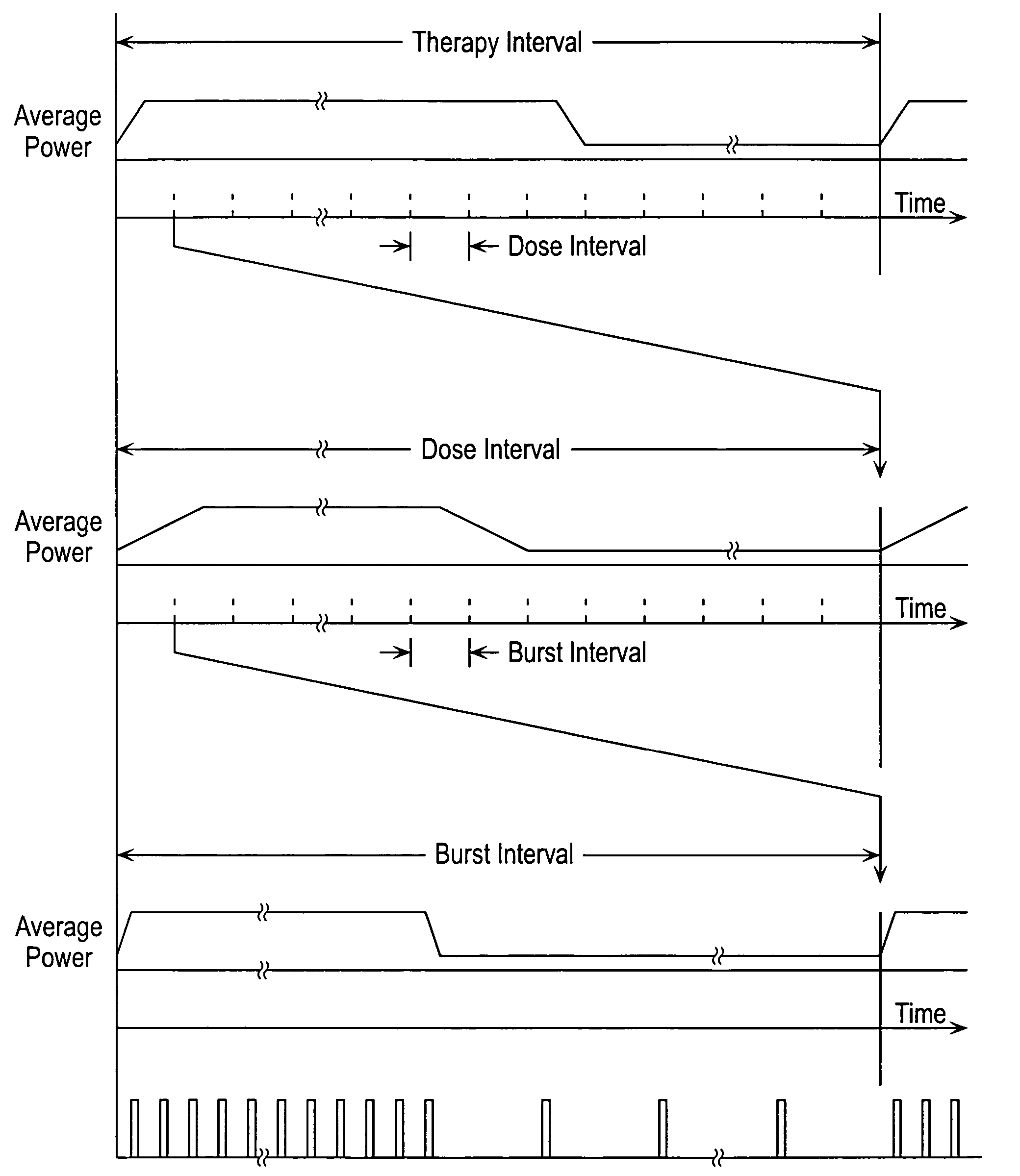
Baroreflex activation is achieved by providing suitable control signals to a baroreflex activation device. A method comprises establishing a therapy interval (possibly on the order of minutes to hours, or possibly of indefinite duration), within the therapy interval, establishing a plurality of dose intervals, and generating an electrical output signal. The electrical output signal has a time dependence such that the average electrical power applied to the baroreflex activation device differs between first and second portions of at least some dose intervals. Another method comprises establishing a series of therapy interval portions, during at least some therapy intervals, establishing a plurality of burst intervals (perhaps having durations commensurate with an interval between heartbeats), and generating an electrical output signal. The electrical output signal has a time dependence such that the average electrical power applied to the baroreflex activation device differs between first and second portions of the therapy intervals and also differs between first and second portions of at least some burst intervals.

Description

[0001]This application is a continuation-in-part of the following U.S. patent applications, the disclosures of which are hereby incorporated by reference:[0002]U.S. patent application Ser. No. 09 / 964,079, filed Sep. 26, 2001 (Robert S. Kieval et al.), titled “Stimulus Regimens for Cardiovascular Reflex Control,” which is a continuation-in-part of U.S. patent application Ser. No. 09 / 671,850, filed Sep. 27, 2000 (Robert S. Kieval et al.), titled “Devices and Methods for Cardiovascular Reflex Control,” now U.S. Pat. No. 6,522,926 issued Feb. 18, 2003;[0003]U.S. patent application Ser. No. 09 / 963,777, filed Sep. 26, 2001 (Robert S. Kieval et al.), titled “Electrode Designs and Methods of Use for Cardiovascular Reflex Control Devices,” which is a continuation-in-part of U.S. patent application Ser. No. 09 / 671,850, filed Sep. 27, 2000 (Robert S. Kieval et al.), titled “Devices and Methods for Cardiovascular Reflex Control,” now U.S. Pat. No. 6,522,926, issued Feb. 18, 2003; and[0004]U.S. ...

Claims


Application Information

Patent Timeline
Patent Type & Authority Patents(United States)
IPC IPC(8): A61N1/18A61N1/32A61N1/05A61N1/36A61N1/08A61N1/365
CPCA61N1/0551A61N1/3627A61N1/36114A61N1/0558A61N1/36007A61N1/36514A61N1/36117
Inventor ROSSING, MARTIN A.KIEVAL, ROBERT S.SERDAR, DAVID J.PERSSON, BRUCE J.
Owner CVRX
Learn More