
Method and apparatus for sensing a time varying current passing through an ion channel

a technology of ion channels and electrical currents, applied in the direction of resistance/reactance/impedence, instruments, material electrochemical variables, etc., can solve problems that are not typically done, and achieve the effect of less overall effect on system noise and capacitance reduction

Active Publication Date: 2009-11-24
ELECTRONICS BIOSCI
View PDF32 Cites 60 Cited by
  • Summary
  • Abstract
  • Description
  • Claims
  • Application Information

AI Technical Summary

Benefits of technology

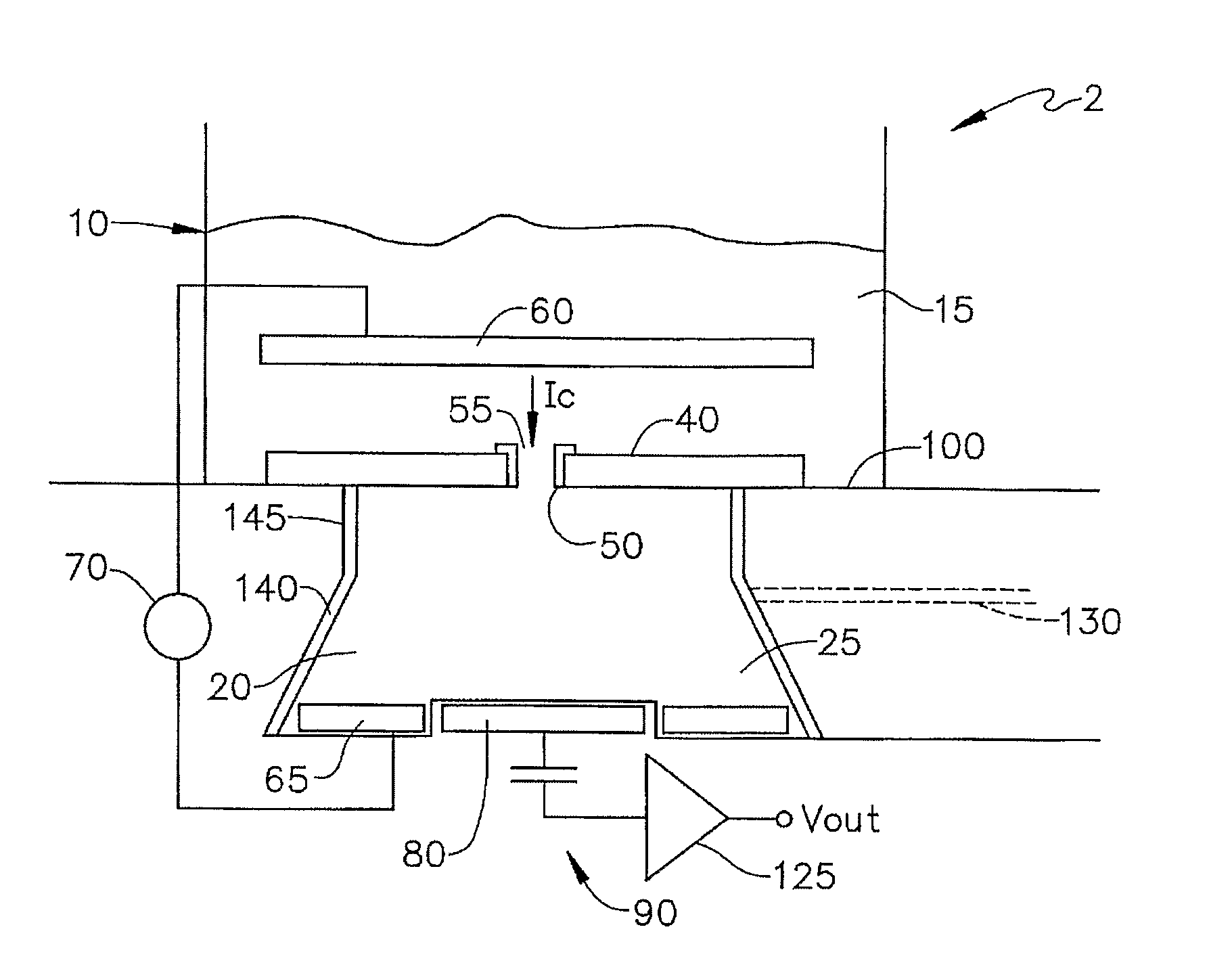
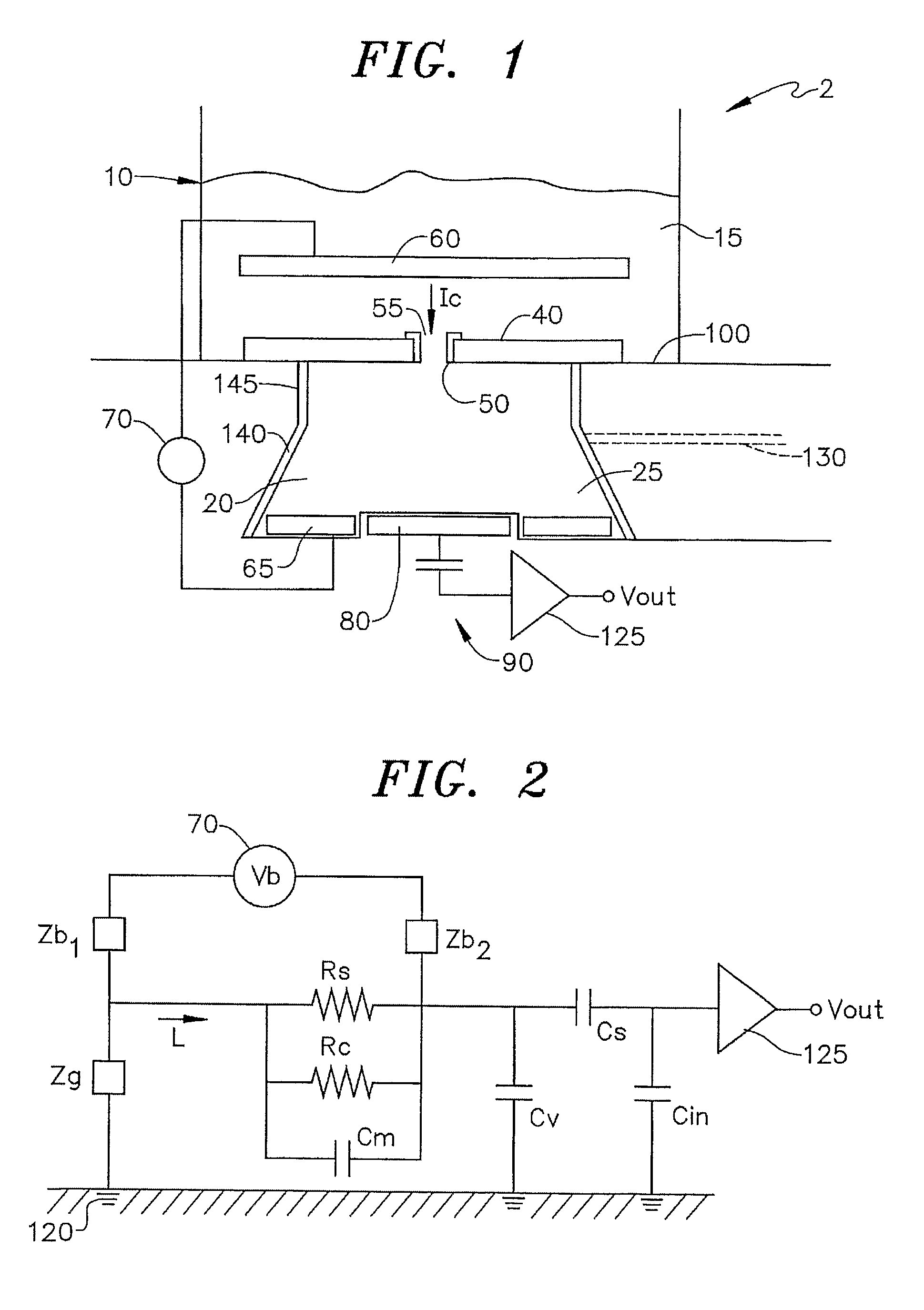
[0021]A benefit of the capacitive method is that, because the impedances of the electrodes and driving voltage circuitry are so high as compared to the electrolyte, electrolyte resistance does not contribute to system noise over a range of typical system values. In some patch clamp measurements, pipette access resistance sets a minimum detectable signal level. Thus, for some experimental situations, the present invention offers higher sensitivity than possible in prior art patch clamp methods.
[0022]In the prior art patch clamp method that is the standard for present measurements, the channel is biased at a fixed voltage that is maintained by feedback if necessary (i.e., voltage clamping). In the case of the present invention, DC potential can be measured directly by resistive electrodes if these are used. In the case of a bias voltage, such electrodes are connected to a very high impedance circuit to prevent current flow that could short the potential of the sensing volume.
[0024]A benefit of capacitive sensing in the measurement configuration described by the invention is that the resulting system noise is, in many configurations, less dependent on the seal resistance between the membrane and the rest of the system than is the traditional patch clamp method. In particular, relatively low values of the seal resistance (<100 MΩ) appear in general to have less of an overall effect on the system noise than the same seal resistance would for the patch clamp method.
[0025]By virtue of their very nature, capacitive sensors have a further benefit for measuring ionic currents in small devices. To measure the variation in ionic current flowing in an ion channel or protein pore, a means must be provided to convert the current to a voltage. This is easily and naturally achieved by the fact that, as an ionic current flows into a confined volume, a net electrostatic charge builds up as the ion current accumulates. This build up charge leads to an increase in the electric potential in a manner analogous to the rise in potential due to the build up of charge during electron flow into a capacitor. In addition to great simplicity, this effect has the very desirable property that, as the volume in question is reduced in size, its capacitance decreases and, as a result, the voltage produced by a given net charge increases.

Problems solved by technology

However, this is not typically done in the prior art due to signal to noise ratio (SNR) considerations.

Method used


Image

  • Method and apparatus for sensing a time varying current passing through an ion channel
  • Method and apparatus for sensing a time varying current passing through an ion channel
  • Method and apparatus for sensing a time varying current passing through an ion channel

Examples


second embodiment

[0045]In accordance with the present invention which is illustrated in FIG. 4 and functionally similar to sensing system 2 described above, a sensing system 2 includes a membrane 40′ located directly on a capacitive sensing electrode 80′ and substrate 100. This geometry is referred to as a supported Membrane, whereas membrane 40, shown in FIG. 1, constitutes a suspended membrane. Membrane 40′ can be supported on a hard surface, such as capacitive sensing electrode 80 and substrate 100 by a variety of methods not shown in FIG. 4 that include: ultra thin viscous films, hydrophilic polymers, soft polymer cushions, aerogels, xerogels, and tethers. With this arrangement, there is no necessity to fabricate sensing volume 20, e.g., by etching a hole in silicon.

third embodiment

[0046]In accordance with the present invention as illustrated in FIG. 5, a sensing system 2″ positions capacitive sensing electrode 80′ near channel 50 either directly in contact or in the same manner as support membrane 40′ shown in FIG. 4. First electrode 60′ is positioned substantially closer to channel 50 in bath 10 and includes a hole 175 to allow the ionic current to enter channel 50. This geometry has the capability of measuring voltage variations directly across channel 50. Locating first electrode 60′ so close to channel 50 (note electrode 60′ could be atop membrane 40′) requires depositing a material similar to that used to support membrane 40′ and fabricating a conducting surface over that material. The presence of electrode 60′ could be used to corral channel 50 in the desired region of membrane 40′. While technically challenging, the resulting embodiment of the invention enables the electric field across channel 50 to be measured directly.

[0047]In general, the present i...


PUM

PropertyMeasurementUnit
thicknessaaaaaaaaaa
thicknessaaaaaaaaaa
thicknessaaaaaaaaaa

Abstract

A capacitive sensing system is used to measure a time-varying ion current through a channel, such as an ion channel or protein pore. Such a capacitive system does not suffer problems of electrode corrosion and, when used with methods to control a build up of ion concentration, allows the use of measurement volumes around the channel with dimensions on a scale of nanometers.

Description

CROSS-REFERENCE TO RELATED APPLICATION[0001]The present application represents a National Stage application of PCT / US2005 / 026181 filed Jul. 22, 2005 entitled “Method and Apparatus For Sensing a Time Varying Current Passing Through an Ion Channel”, and claims the benefit of U.S. Provisional Patent Application Ser. No. 60 / 590,351 filed Jul. 23, 2004 entitled “Sensing Means For Ion Channels and Protein Pores.”[0002]This application claims the benefit of U.S. Provisional Patent Application Ser. No. 60 / 590,351 filed Jul. 23, 2004.STATEMENT REGARDING FEDERALLY SPONSORED RESEARCH OR DEVELOPMENT[0003]The U.S. Government has a paid-up license in this invention and the right in limited circumstances to require the patent owner to license others on reasonable terms as provided for by the terms of Contract A9550-05-C0050 awarded by the U.S. Air Force Office of Scientific Research.BACKGROUND OF THE INVENTION[0004]The present invention pertains to the art of electrical sensing devices and, more p...

Claims


Application Information

Patent Timeline
Patent Type & Authority Patents(United States)
IPC IPC(8): G01R27/26
CPCG01N33/48728G01N27/22G01N33/48707G01R19/00G01R27/2605
Inventor HIBBS, ANDREW D.DUGAN, REGINA E.
Owner ELECTRONICS BIOSCI
Learn More