Eureka AIR delivers breakthrough ideas for toughest innovation challenges, trusted by R&D personnel around the world.

Method of forming a rotary device

a rotary device and rotor technology, applied in the direction of machines/engines, manufacturing tools, liquid fuel engines, etc., can solve the problems of increasing the weight of time-consuming, wasteful, and expensive to employ matching between the rotor and the stator, so as to reduce the need for lubrication or eliminate the need, the effect of reducing the size, weight, and the overall system dimensions

Inactive Publication Date: 2009-11-24
STAFFEND GILBERT
View PDF60 Cites 14 Cited by
  • Summary
  • Abstract
  • Description
  • Claims
  • Application Information

AI Technical Summary

Benefits of technology

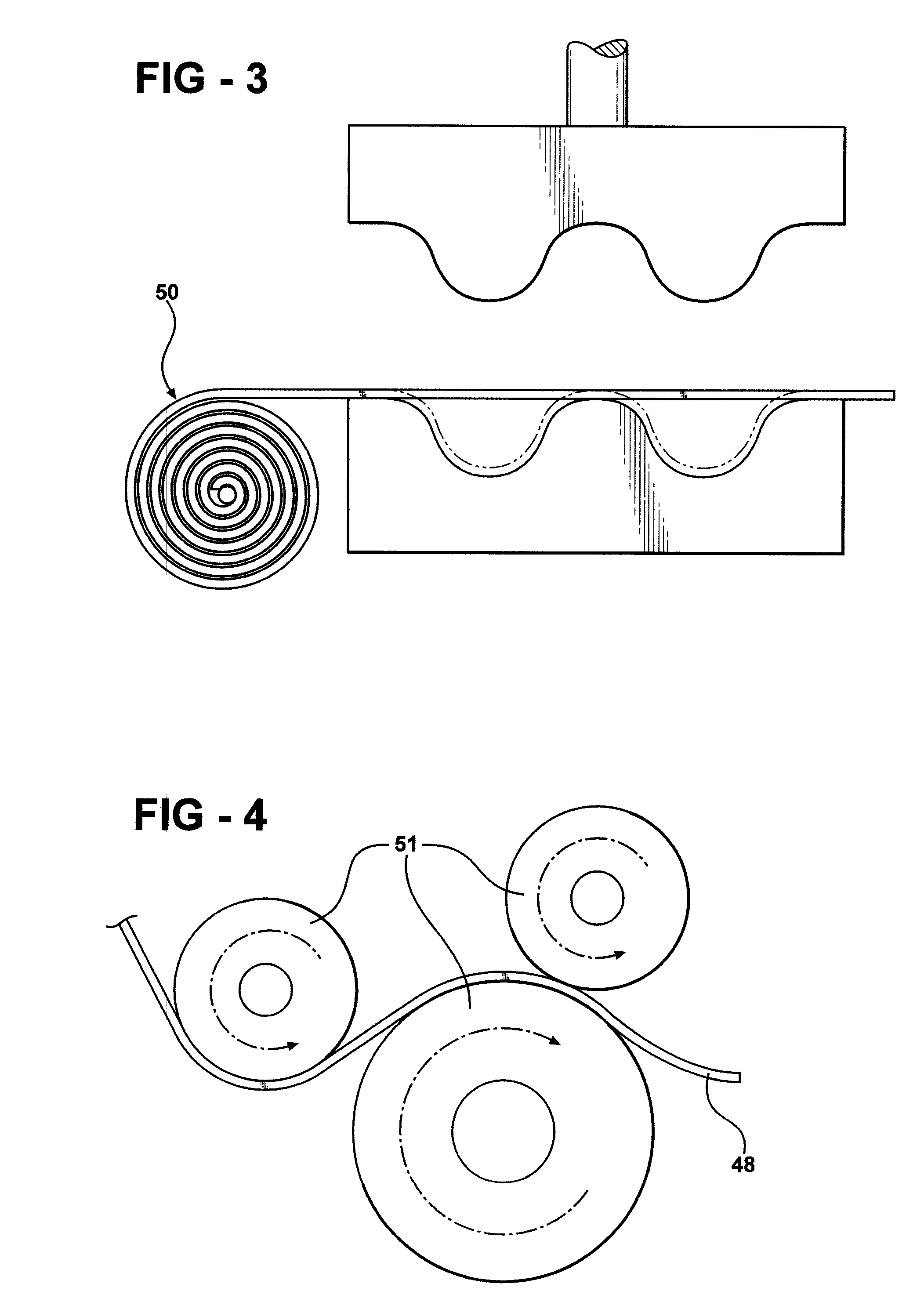
"The present invention is a method of constructing a rotary device by roll forming a first ribbon of material to achieve a desired profile of an outer peripheral wall, and securing it in place. A second ribbon of material is then roll formed to achieve a desired profile of an inner peripheral wall. By using roll forming instead of traditional castings, the invention achieves several manufacturing benefits, including reduced weight, reduced need for lubrication, and improved surface tolerances. The invention also eliminates excess casting weight and seal and friction issues typical with traditional rotary devices. The method is efficient and cost-effective."

Problems solved by technology

The use of cast components adds a significant amount of weight to the rotary device.
Additionally, because the circularity of machining the cast components varies greatly between castings, it can become very time consuming, wasteful, and expensive to employ matching between the rotor and the stator.

Method used


Image

  • Method of forming a rotary device
  • Method of forming a rotary device
  • Method of forming a rotary device

Examples


Embodiment Construction

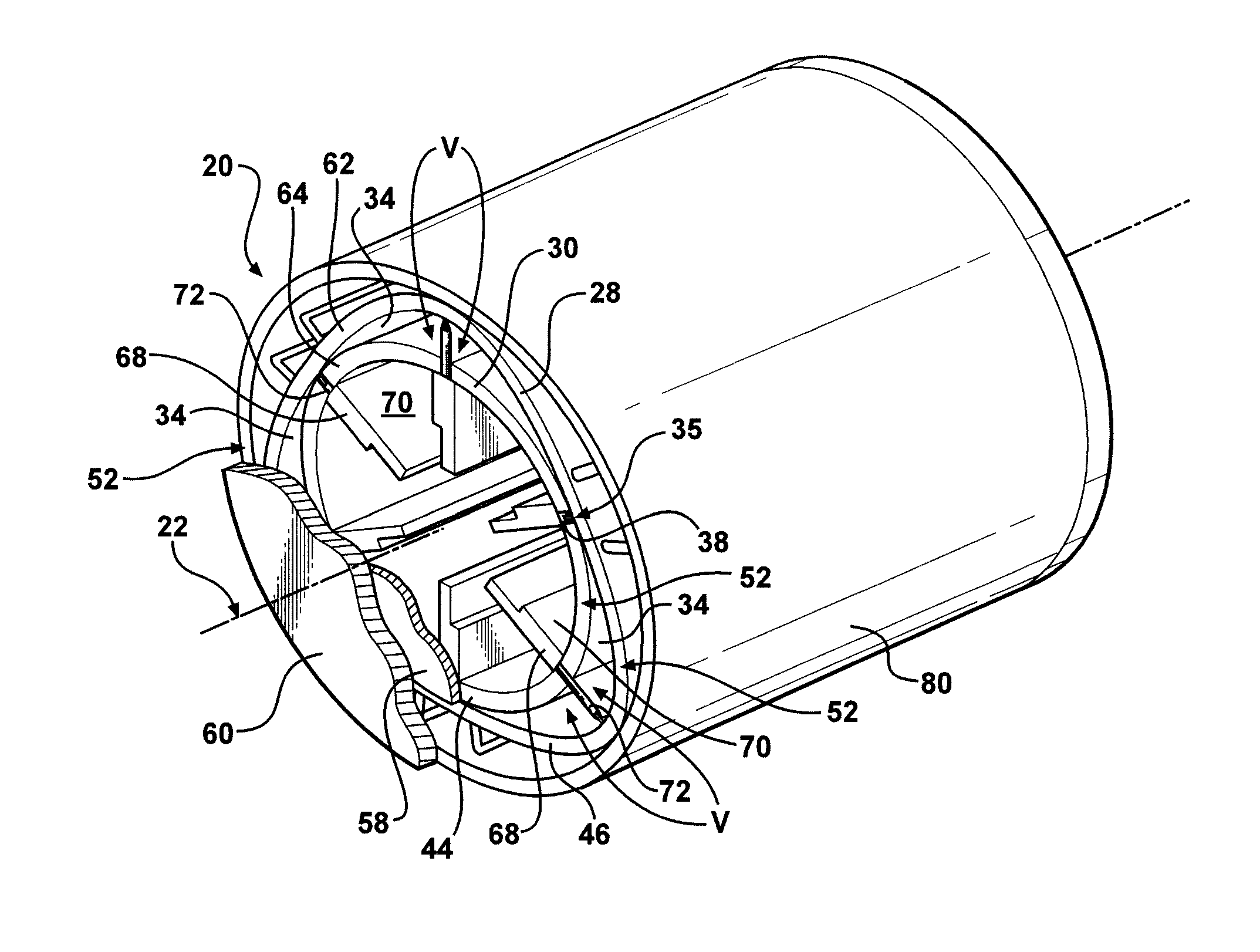
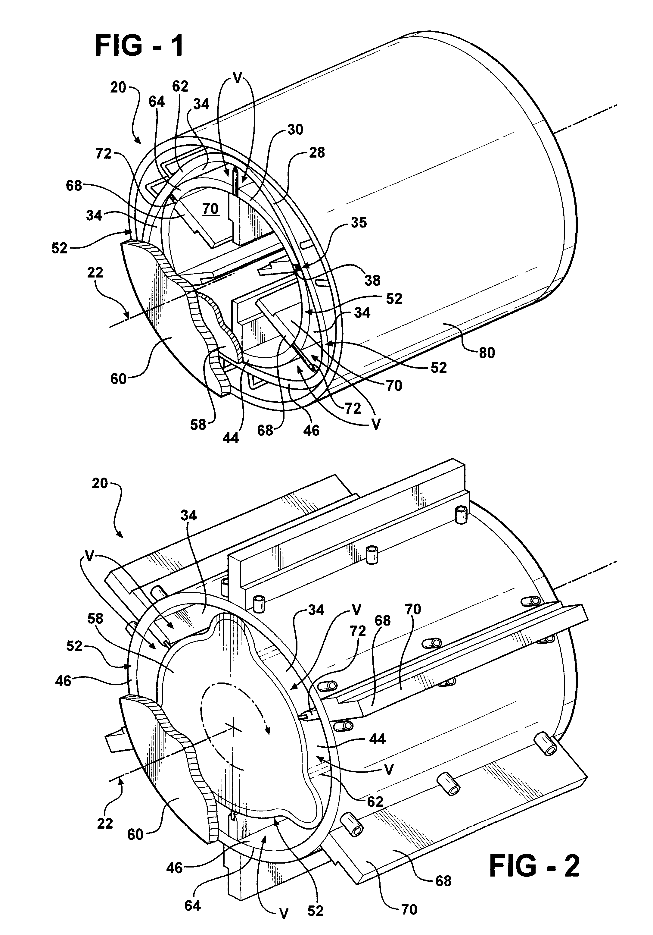
[0028]The present invention relates to a rotary device, such as a rotary engine. The rotary device is shown generally at 20 in FIGS. 1 and 2. The rotary device 20 includes an outer hub 28 and an inner hub 30 disposed within the outer hub 28. Each of the hubs 28, 30 are generally centered about an axis 22 such that one of the hubs 28, 30 rotates with respect to the other hub 28, 30 about the axis 22. Each of the hubs 28, 30 represents either a stator or a rotor where the rotor is rotatable with respect to the stator about the axis 22. Therefore, the stator is static, i.e., the stator does not rotate, and the rotor is generally concentric with, and rotatable with respect to, the stator about the axis 22. In one embodiment, the stator surrounds the rotor on the axis 22. In an alternative embodiment, the rotor surrounds the stator about the axis 22. A bearing may be disposed on the axis 22 for facilitating rotation of the rotor with respect to the stator 24. Alternatively, the relative ...


PUM

PropertyMeasurementUnit
perimeteraaaaaaaaaa
thickaaaaaaaaaa
weightaaaaaaaaaa

Abstract

The present invention is a method of constructing a rotary device which as an outer hub and an inner hub disposed within the outer hub. One of the inner and outer hubs is rotatable with respect to the other one of the inner and outer hubs about an axis. A ribbon of material extends between opposite ends and is roll formed to achieve a desired profile of an inner and outer peripheral wall of the inner and outer hub, respectively. The roll formed ribbons of material are each secured to maintain the desired profile and achieve the respective peripheral wall. The inner peripheral wall is inserted inside the outer peripheral wall such that the outer peripheral wall surrounds the inner peripheral wall.

Description

CROSS REFERENCE TO RELATED APPLICATION[0001]This application claims the benefit U.S. Provisional Patent Application Ser. No. 60 / 718,029 filed Sep. 16, 2005 and is a continuation-in-part of U.S. patent application Ser. No. 11 / 133,824 filed on May 20, 2005, which claimed priority to U.S. Provisional Patent Application Ser. No. 60 / 572,706 filed May 20, 2004, and is related to U.S. Ser. No. 11 / 532,385, filed on the same date as this application and entitled “Transmission Between Rotary Devices”, and is related to U.S. Ser. No. 11 / 532,366, filed on the same date as this application and entitled “Method of Decoupling Using a Rotary Device,” which are hereby incorporated by reference.BACKGROUND OF THE INVENTION[0002]1. Field of the Invention[0003]The invention generally relates to a method of forming a rotary device.[0004]2. Description of the Related Art[0005]Traditional rotary devices include a stator and rotor which is rotatable with respect to the stator about an axis. These rotary dev...

Claims


Application Information

Patent Timeline
Patent Type & Authority Patents(United States)
IPC IPC(8): B21C37/06B21B15/00B21D13/00
CPCF01C1/34F01C1/3566F01C21/08F04C2/3446F01C21/106F05C2203/08F04C2230/20F04C2230/26
Inventor STAFFEND, GILBERT
Owner STAFFEND GILBERT
Why Eureka
Eureka Blog
Learn More