Eureka AIR delivers breakthrough ideas for toughest innovation challenges, trusted by R&D personnel around the world.

System for precharging a DC link in a variable speed drive

a variable speed drive and pre-charging technology, applied in emergency protective arrangements for limiting excess voltage/current, refrigeration components, light and heating equipment, etc., can solve the problems of inrush current, cost and size of its components, and can be damaging to the components so as to reduce the size and reduce the cost of the variable speed drive

Inactive Publication Date: 2009-11-17
YORK INT CORP
View PDF47 Cites 22 Cited by
  • Summary
  • Abstract
  • Description
  • Claims
  • Application Information

AI Technical Summary

Benefits of technology

[0017]One advantage of the present invention is that it is small and compact and can thereby reduce the size of the variable speed drive.
[0018]Another advantage of the present invention is that it reduces the cost of the variable speed drive by eliminating the need for expensive parts.
[0019]Still another advantage of the present invention is that it increases the reliability of the variable speed drive by eliminating electromechanical parts subject to routine wear and tear.
[0020]A further advantage of the present invention is increased efficiency of the variable speed drive due to the absence of reverse recovery phenomena in silicon carbide controlled rectifiers.

Problems solved by technology

This large current, referred to as an inrush current, can be damaging to the components of the VSD.
The main disadvantage of this method is in the cost and size of its components, in particular of the supply contactor, which can negatively impact the cost and size of the entire VSD.
The embedded diode rectifier presents a problem for the precharge of VSDs that use IGBT modules because the first precharge method (precharge and supply contactors and resistors) described above must be used to precharge the DC link.
This places additional cost and size burden on VSDs having IGBT modules for the rectifier or converter.

Method used


Image

  • System for precharging a DC link in a variable speed drive
  • System for precharging a DC link in a variable speed drive
  • System for precharging a DC link in a variable speed drive

Examples


Embodiment Construction

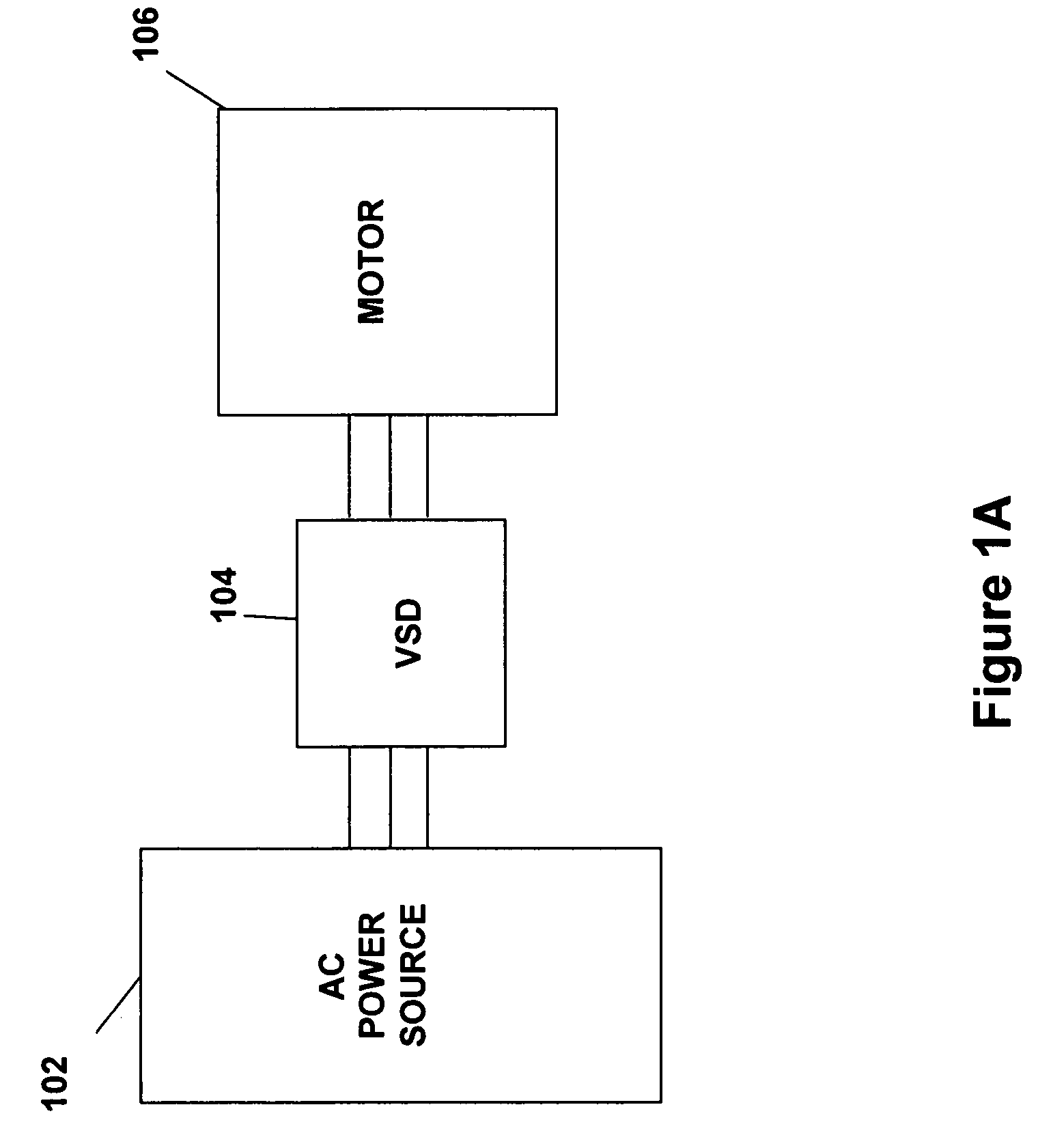
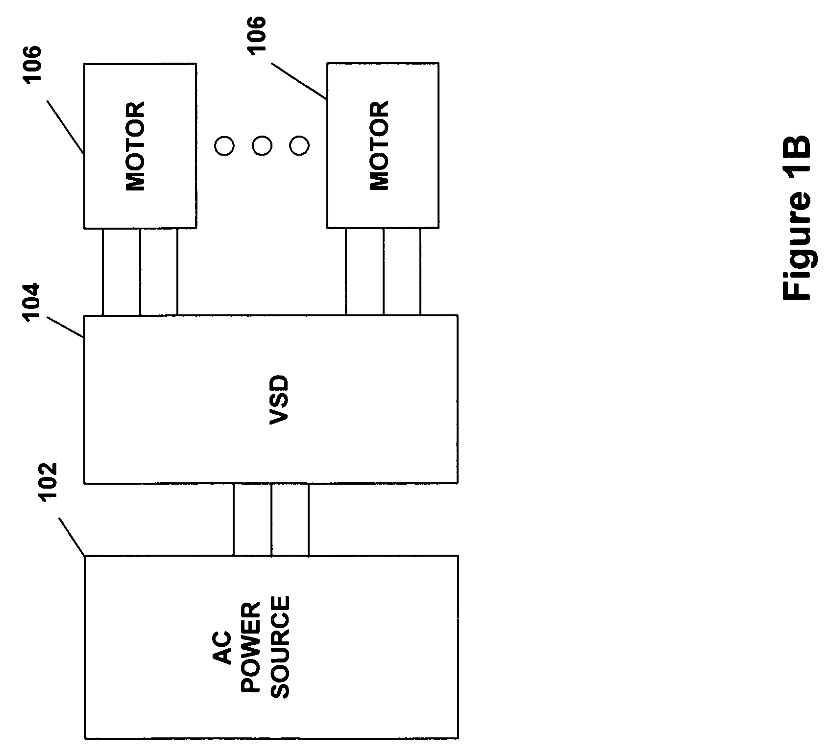
[0029]FIGS. 1A and 1B illustrate generally system configurations of the present invention. An AC power source 102 supplies a variable speed drive (VSD) 104, which powers a motor 106 (see FIG. 1A) or motors 106 (see FIG. 1B). The motor(s) 106 is preferably used to drive a corresponding compressor of a refrigeration or chiller system (see generally, FIG. 3). The AC power source 102 provides single phase or multi-phase (e.g., three phase), fixed voltage, and fixed frequency AC power to the VSD 104 from an AC power grid or distribution system that is present at a site. The AC power source 102 preferably can supply an AC voltage or line voltage of 200 V, 230 V, 380 V, 460 V, or 600 V, at a line frequency of 50 Hz or 60 Hz, to the VSD 104 depending on the corresponding AC power grid.

[0030]The VSD 104 receives AC power having a particular fixed line voltage and fixed line frequency from the AC power source 102 and provides AC power to the motor(s) 106 at a desired voltage and desired frequ...


PUM


Abstract

A variable speed drive with a converter that is controllable to precharge a DC link is provided. The variable speed drive also includes an inverter. The converter converts a fixed line frequency, fixed line voltage AC power from an AC power source into DC power. The DC link filters the DC power from the converter. Finally, the inverter is connected in parallel with the DC link and converts the DC power from the DC link into a variable frequency, variable voltage AC power. The converter includes a plurality of pairs of power switches, wherein each pair of power switches includes a reverse blocking power switch arrangement connected in anti-parallel to another reverse blocking power switch arrangement. Alternatively, each pair of power switches includes a reverse blocking power switch connected in anti-parallel with a silicon carbide controlled rectifier.

Description

CROSS-REFERENCE TO RELATED APPLICATIONS[0001]This Application is a continuation-in-part of application Ser. No. 11 / 073,830, filed Mar. 7, 2005, which is a continuation-in-part of application Ser. No. 11 / 068,999, filed Mar. 1, 2005.BACKGROUND OF THE INVENTION[0002]The present invention relates generally to variable speed drives. More specifically, the present invention relates to a system for precharging the DC link in a variable speed drive using insulated gate bipolar transistors in the rectifier or converter.[0003]A variable speed drive (VSD) for heating, ventilation, air-conditioning and refrigeration (HVAC&R) applications typically includes a rectifier or converter, a DC link, and an inverter. The rectifier or converter converts the fixed line frequency, fixed line voltage AC power from an AC power source into DC power. The DC link filters the DC power from the converter and typically contains a large amount of electrical capacitance. Finally, the inverter is connected in parall...

Claims


Application Information

Patent Timeline
Patent Type & Authority Patents(United States)
IPC IPC(8): H02J5/00
CPCH02H9/001H02M1/36H02M7/125H02M5/4585Y02B70/1483Y02B70/10H02P27/04H02M7/12
Inventor SCHNETZKA, HAROLD R.
Owner YORK INT CORP
Why Eureka
Eureka Blog
Learn More