
Neural network for aeroelastic analysis

a neural network and aeroelastic analysis technology, applied in the field of aeroelastic analysis, can solve the problems of exceedingly costly aircraft downed flight time, affecting the aeroelastic characteristics of aircraft, and expensive process of aeroelastic analysis

Active Publication Date: 2009-11-10
THE BOEING CO
View PDF6 Cites 13 Cited by
  • Summary
  • Abstract
  • Description
  • Claims
  • Application Information

AI Technical Summary

Benefits of technology

The patent describes a system and method for analyzing the stability of structures using a neural network. The system determines the input parameters that contribute to the stability of a structure, such as mass and location, and creates a model of the structure that can be analyzed using a finite element model. The neural network is trained using input samples and weights to create a non-linear transfer function that predicts the stability of the structure when given different input parameters. The technical effect of this system is that it allows for more accurate and efficient analysis of the stability of structures, which can help in designing safer and more reliable structures.

Problems solved by technology

Any repair or alteration of an aircraft structure may affect the aeroelastic characteristics of the aircraft.
Because the safety of the aircraft may be in question after performance of the repair, the time required to perform the aeroelastic analysis may represent a period in which the aircraft is grounded and unavailable.
The process of performing the aeroelastic analysis is costly and having downed flight time for aircraft is exceedingly costly.

Method used


Image

  • Neural network for aeroelastic analysis
  • Neural network for aeroelastic analysis
  • Neural network for aeroelastic analysis

Examples


Embodiment Construction

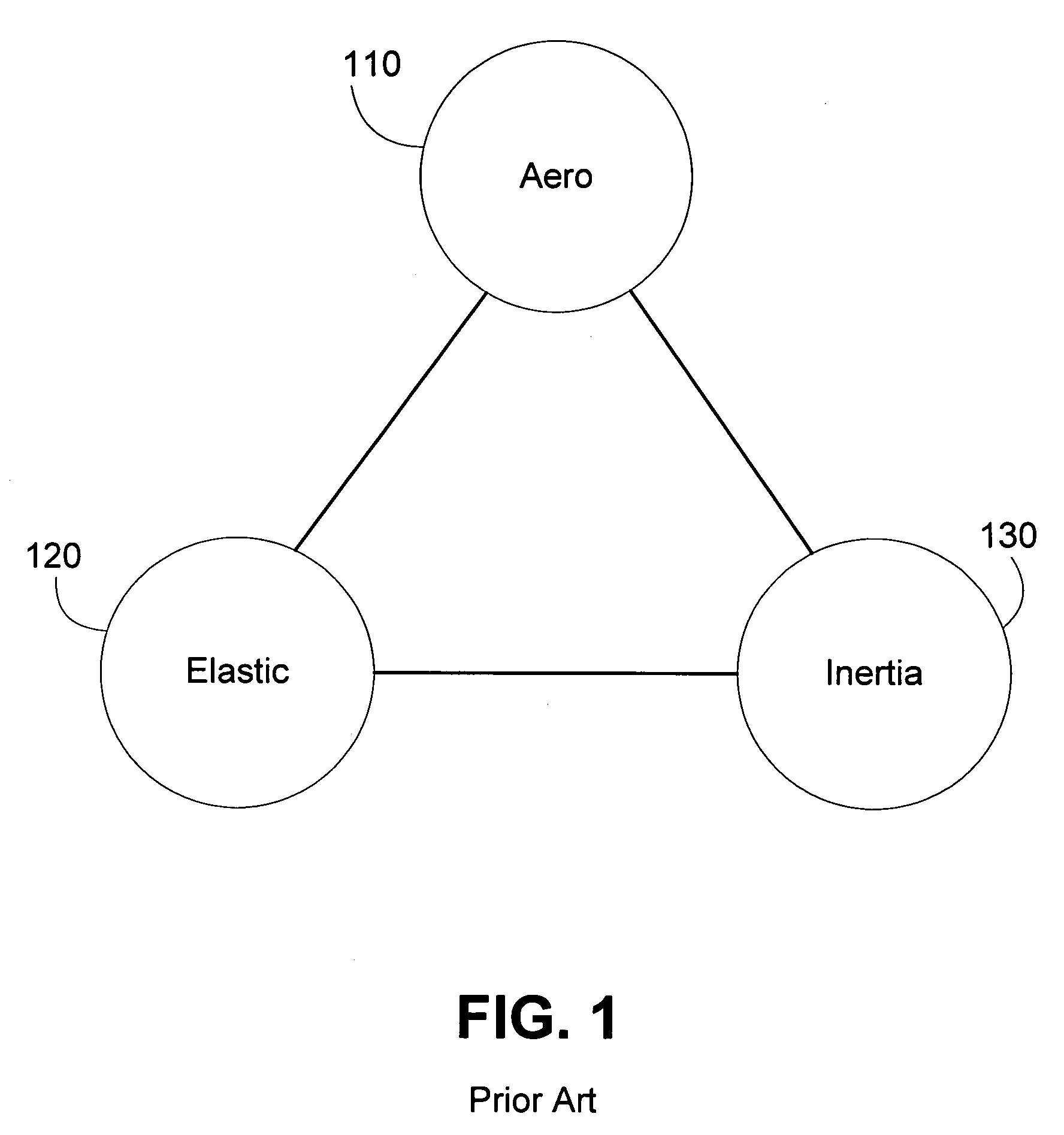
[0024]A system and method for performing aeroelastic flutter analysis based in part on a neural network. A structure can be modeled for flutter analysis. The model can resemble a finite element model used for structural analysis. One or more parameters contributing to the flutter characteristics can be defined and constrained. For example, each of the parameters may be constrained to a predetermined range or set. One or more positions or locations on the model can be configured such that one or more of the parameters may be altered at each of the one or more locations.

[0025]A set of input parameters can be determined, with input parameters corresponding to at least a subset of available positions on the model. The set of input parameters are used as inputs to a flutter analysis. Results of the flutter analysis for each of the input parameters can be determined using, for example, a finite element structure analysis followed by interpretation of the results in a flutter analysis. The...


PUM


Abstract

A system and method of performing aeroelastic analysis using a neural network. Input parameters, such as mass and location, contributing to aeroelastic characterization are determined and constrained. A model of a structure to be analyzed can be constructed. The model can include a number of locations where the input parameters can be varied. The aeroelastic characteristic of the structure can be analyzed using a finite element model to determine a number of output characteristics, each of which can correspond to at least one of a plurality of input samples. A neural network can be generated for determining the aeroelastic characteristic based on input parameters. The input sample / output characteristic pairs can be used to train the neural network. The weights and bias values from the trained neural network can be used to generate a non-linear transfer function that generates the aeroelastic characteristic in response to input parameters.

Description

BACKGROUND OF THE DISCLOSURE[0001]1. Field of the Disclosure[0002]The disclosure relates generally to the field of aeroelastic analysis. More particularly, the present disclosure relates to a neural network for aeroelastic analysis.[0003]2. Description of Related Art[0004]Aeroelastic analysis is typically used in the aerospace industry to characterize aircraft and structures that form part of or that affect the stability of the aircraft. Aircraft are increasingly designed for and subjected to longer service lives. As a result, one or more structures on an aircraft may be repaired or altered during the life of the structure. Any repair or alteration of an aircraft structure may affect the aeroelastic characteristics of the aircraft.[0005]To ensure that a structural repair or modification does not detrimentally affect the safety or flight characteristics of the aircraft, the repaired or modified structure may be subjected to aeroelastic analysis, such as aeroelastic stability or flutt...

Claims


Application Information

Patent Timeline
Patent Type & Authority Patents(United States)
IPC IPC(8): G06E1/00G06E3/00G06G7/00G06F15/00G06F15/18G06F19/00G06N3/06G06N3/063G06N3/10
CPCG06N3/10
Inventor HAUDRICH, DARIN P.PITT, DALE M.
Owner THE BOEING CO
Learn More