
Timepiece having rotatable and detachable bezel

a timepiece and bezel technology, applied in the field of timepieces of wristwatches, can solve the problems of poor the deformation of the case body and the rotary bezel, and the drawback so as to promote the rotation operability of the rotary bezel and avoid the effect of being caugh

Active Publication Date: 2009-11-10
SEIKO INSTR INC
View PDF2 Cites 11 Cited by
  • Summary
  • Abstract
  • Description
  • Claims
  • Application Information

AI Technical Summary

Benefits of technology

[0014]In the invention, the holding member can be formed by a shape in correspondence with a shape of a ring-like groove of the case body or a shape of the guide groove of the rotary bezel. Further, the holding member can be formed by a metal of stainless steel, titanium or the like or a hard synthetic resin or the like. Along therewith, the holding member may be formed by selecting a material having a small friction resistance with a material forming the case body, for example, when the holding member is formed by a ferrous material in a case in which the case body is made of titanium, the constitution is preferable in that wear of the ring-like groove in accordance with an operation of rotating the rotary bezel can be restrained.
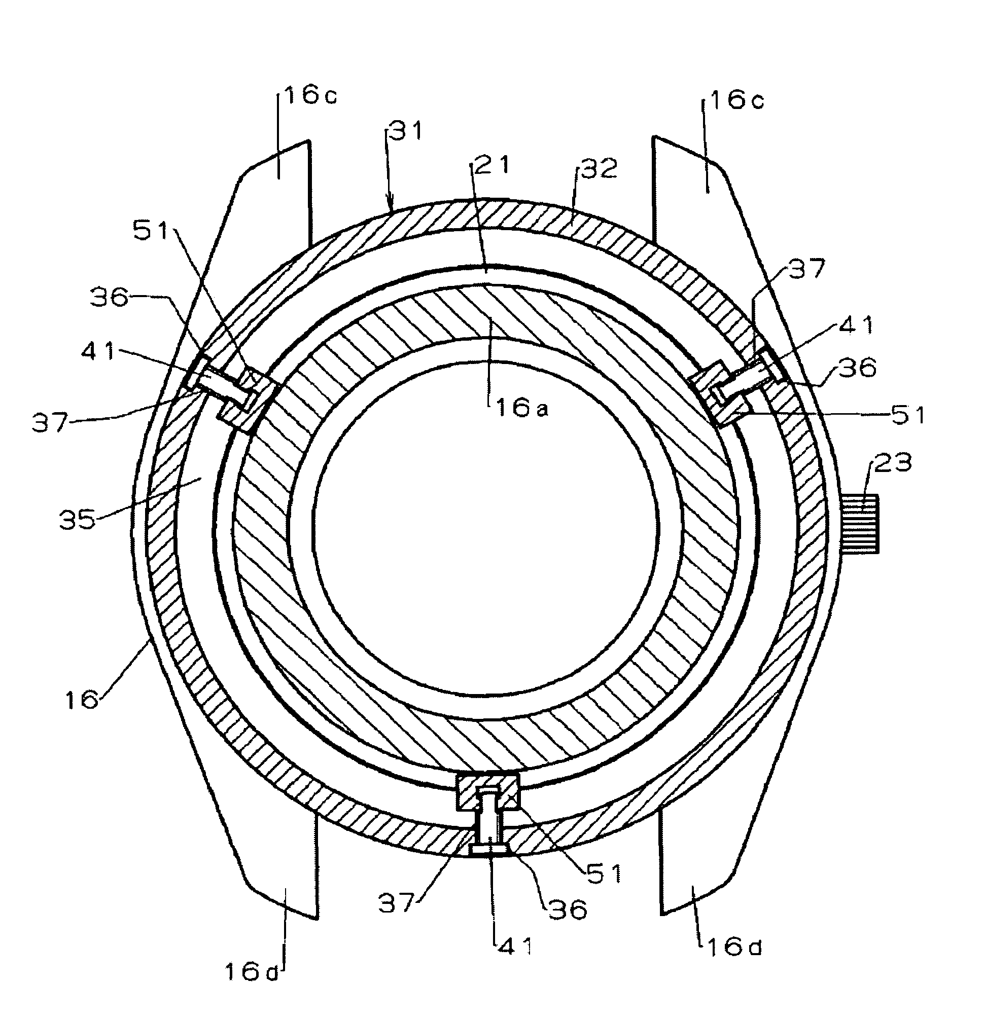
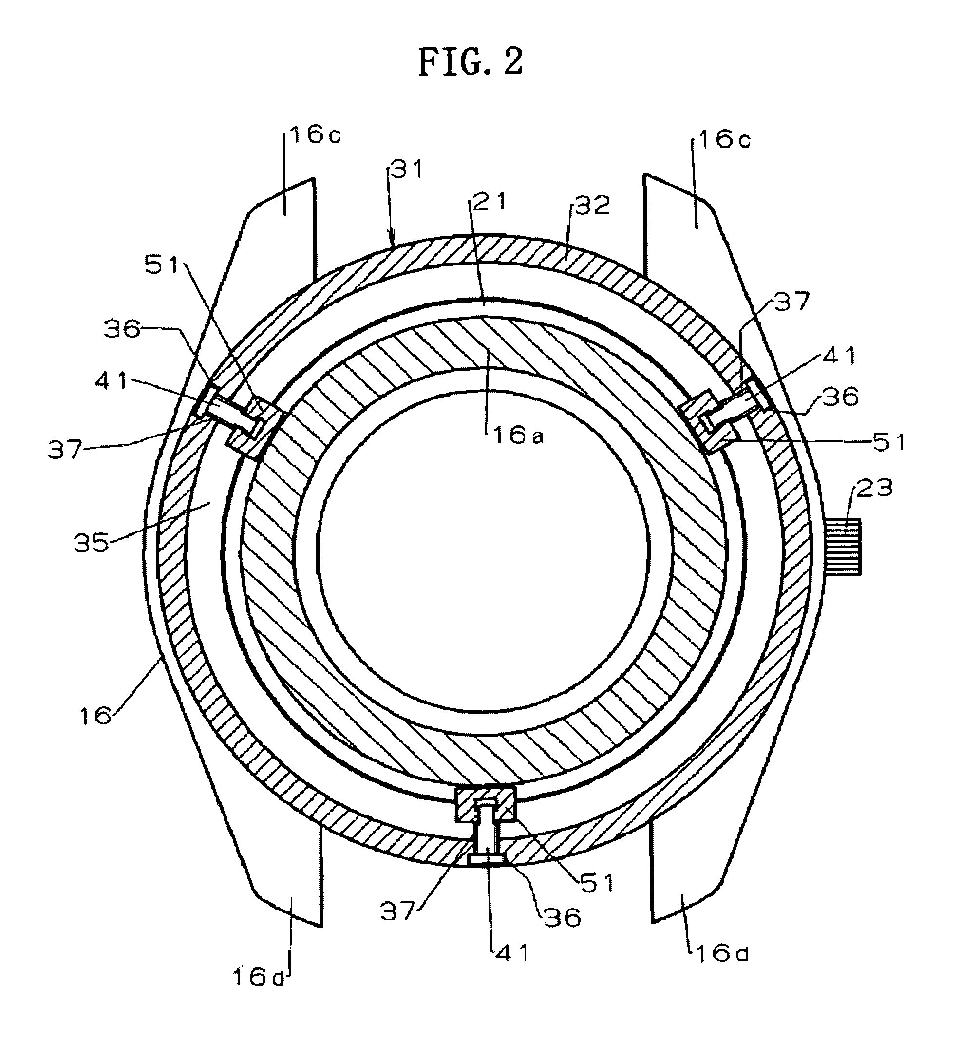
[0018]In accordance with another aspect of the invention, the holding member for preventing detachment of the rotary bezel from the case body is supported by the rotary bezel and is not arranged on an outer side of the rotary bezel. Therefore, the holding member or the like does not hamper the operation of rotating the rotary bezel. Furthermore, the ring-like groove of the case body is covered to be concealed by the rotary bezel, and the total of the outer peripheral face of the fitting portion of the rotary bezel is exposed, and therefore, the thickness of the bezel portion touched by the finger of the user in operating to rotate the rotary bezel is ensured to be large and the finger is easy to be caught thereby.
[0019]Further, as described above, the total of the outer peripheral face of the fitting portion of the rotary bezel is exposed, and therefore, the constitution is advantageous in designing the rotary bezel. In addition thereto, the holding member which is not arranged on the outer side of the rotary bezel does not constitute a hindrance when the rotary bezel is enlarged. Therefore, the large-diameter formation of the rotary bezel can be achieved without enlarging the case body, therefore, a restriction of the total of the timepiece in view of design is inconsiderable.
[0023]According to the mode of the invention, a part for preventing the holding member from being detached from the operating screw is not needed and an integration of connecting the holding member and the operating screw can be carried out by time and labor of only penetrating the fitting shaft portion attached with the head to the horizontal hole. Further, the head of the fitting shaft portion in correspondence with a part for preventing the holding member from being detached from the operating screw is contained in the vertical hole of the holding member as described above, and therefore, it is not necessary to deeply form the ring-like groove in consideration of the part. Therefore, since the ring-like groove can be made shallow, the fitting portion of the case body formed with the ring-like groove can be prevented from having a large diameter in view of maintaining a wall thickness of achieving a strength necessary therefor.
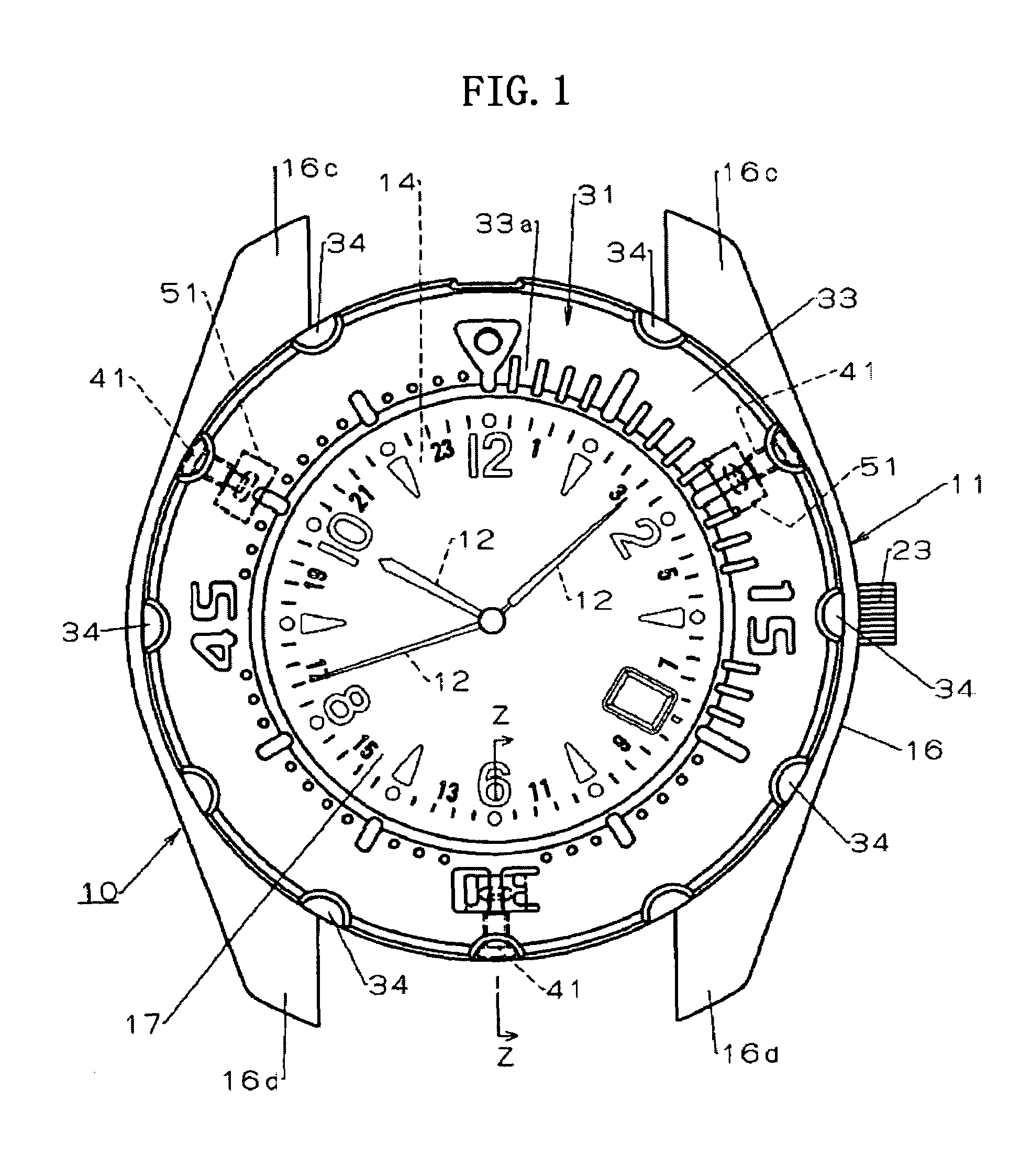
[0026]In a preferable mode of the invention, the head portion of the operating screw is projected from an outer peripheral face of the fitting portion in a state of arranging the holding member at the holding position. In the invention, it is preferable to constitute the head portion of the operating screw in a semispherical shape, further, when projected portions in a semispherical shape projected integrally from the outer peripheral face are provided at the fitting portion at intervals, and the head portion of the operating screw is disposed in the alignment of the projected portions, the finger is further easy to be caught thereby, and therefore, the constitution is preferable.
[0028]According to the invention, the rotary bezel can be attached and detached without being accompanied by deformation of the rotary bezel and the case body, further, in addition to the fact that the finger is easy to be caught by the rotary bezel, there is not a member of hampering the rotational operation at a surrounding of the rotary bezel, and therefore, the rotation operability of the rotary bezel can be promoted and there is not a member around the rotary bezel, and therefore, a timepiece without bringing about large-sized formation of the case body when the rotary bezel is enlarged in view of design can be provided.

Problems solved by technology

The technology of the latter is excellent in that a drawback of the technology of the former, that is, a drawback of deforming the case body and the rotary bezel in accordance with prying to detach the rotary bezel in maintenance, can be resolved.
However, there is the following drawback in the technology of the latter.
That is, the surrounding of the rotary bezel is covered by the outer peripheral wall of the case body, and therefore, a thickness for the attachment of the finger in operating to rotate the rotary bezel is obliged to be thinned and, thereby, the operability of the rotary bezel is poor.
In addition thereto, the operability of the rotary bezel is poor since in operating to rotate the rotary bezel, since rotation is hampered by touching the finger of a user to the pair of engaging members arranged on the outer side of the rotary bezel.

Method used


Image

  • Timepiece having rotatable and detachable bezel
  • Timepiece having rotatable and detachable bezel
  • Timepiece having rotatable and detachable bezel

Examples


Embodiment Construction

[0036]A first embodiment of the invention will be explained in reference to FIG. 1 through FIG. 6.

[0037]In FIG. 1, notation 10 designates a timepiece, for example, a portable timepiece, specifically, a wristwatch. A timepiece movement 13 for driving an indicating hand 12 (refer to FIG. 1), a dial 14 attached to the timepiece movement 13, and a frame-like member 15 for holding the timepiece movement 13 at a timepiece exterior assembly 11 and the like as shown by FIG. 3 and FIG. 4 are contained in the timepiece exterior assembly 11 provided to the wristwatch 10. The indicating hand 12 and the dial 14 constitute a timepiece display portion.

[0038]As shown by FIG. 3 and FIG. 4, the timepiece exterior assembly 11 is formed by attaching a cover glass 17 as a transparent cover and a case back 18 to a case body 16 made in a ring or ring-like shape by a metal. Further, the transparent cover can also be formed of a transparent synthetic resin. A front side of the case body 16 is integrally for...


PUM


Abstract

A timepiece has a case body and a bezel rotatably and detachably connected to the case body. A ring-shaped guide groove formed in the bezel opposes a ring groove formed in the case body, and a plurality of holding members are slidable in the guide groove into and out of the ring groove to respectively prevent and permit detachment of the bezel from the case body. A plurality of operating screws are screwed into the bezel from an outer side thereof and are rotatably connected at their front end portions to respective holding members. Rotation of the operating screws in tightening and loosening directions moves the holding members into and out of the ring groove.

Description

BACKGROUND OF THE INVENTION[0001]1. Field of the Invention[0002]The present invention relates to a timepiece of a wristwatch or the like including a rotatable bezel.[0003]2. Related Art[0004]In a background art, there is known a wristwatch attached with a rotary bezel at a case body by rotatably fitting the rotary bezel to the case back by making two projected portions caught by each other such that the projected portions provided at an inner periphery of the rotary bezel rides over the projected portion provided at an outer periphery of a ring-like portion of the case body surrounding a transparent cover covering a time display portion to a lower side (refer to, for example, Patent Reference 1).[0005]Further, there is known a wristwatch in which in order to attach a rotary bezel to a case body without depending on such a catching structure, a ring-like groove is formed at an outer peripheral face of the rotary bezel fitted to an outer periphery of a ring-like portion of the case bo...

Claims


Application Information

Patent Timeline
Patent Type & Authority Patents(United States)
IPC IPC(8): G04B39/00
CPCG04B19/283
Inventor HIRANUMA, HARUKIIMAI, KAZUTAKATAKEDA, KOREMOTO
Owner SEIKO INSTR INC
Learn More