
Adaptive high frequency laser sonar system

a high-frequency laser and sonar technology, applied in the field of acoustic sensors, can solve the problems of limited acoustic frequencies utilized by the array, unsuitable for use as an underwater acoustic sensor, and the inability of laser interferometers to scan the boundary surface, so as to prevent the noise of the housing

Inactive Publication Date: 2009-11-03
COUNSEL THE UNITED STATES OF AMERICA NAVAL UNDERSEA WARFARE CENT DIV NEWPORT OFFICE OF COUNSEL
View PDF5 Cites 4 Cited by
  • Summary
  • Abstract
  • Description
  • Claims
  • Application Information

AI Technical Summary

Benefits of technology

The system achieves continuous acoustic aperture sampling with an upper cut-off frequency of 74 MHz, effectively isolating from structure-borne noise and providing clear, undistorted acoustic signal reception from various angles, enhancing the accuracy of underwater acoustic detection.

Problems solved by technology

Thus, the acoustic frequencies utilized by the array are limited by the sensor spacing
It is suggested that various characteristics of the disclosed system make it unsuitable for use as an underwater acoustic sensor.
The laser interferometer is not capable of scanning the boundary surface to conduct beamforming.
The boundary surface is not sufficiently stable to clearly determine acoustic vibrations.
Furthermore, the laser interferometer is not insulated from vehicle vibrations.
This distorted the time series measurements made on the surface of the panel.
Antonelli et al. disclose an air / water acoustic window, but they don't disclose the use of vibration isolation for the window and the laser vibrometer.
As above, it has been found that this lack of isolation interferes with the reception of external acoustic signals.

Method used


Image

  • Adaptive high frequency laser sonar system
  • Adaptive high frequency laser sonar system
  • Adaptive high frequency laser sonar system

Examples


Embodiment Construction

[0023]In its simplest form, Euler's equation for a propagating harmonic plane wave reduces to

p(x,t)=ρcv(x,t),  (1)

where p(x,t) is acoustic pressure and ρcv(x,t) is the product of the medium's characteristic impedance ρc and acoustic particle velocity v(x,t). Thus, measuring acoustic pressure with an array of conventional hydrophones is equivalent to measuring acoustic particle velocity with an array of velocity sensors. This equivalence has been the basis for sonobuoy designs for decades and, more recently, for innovative submarine sonar systems.

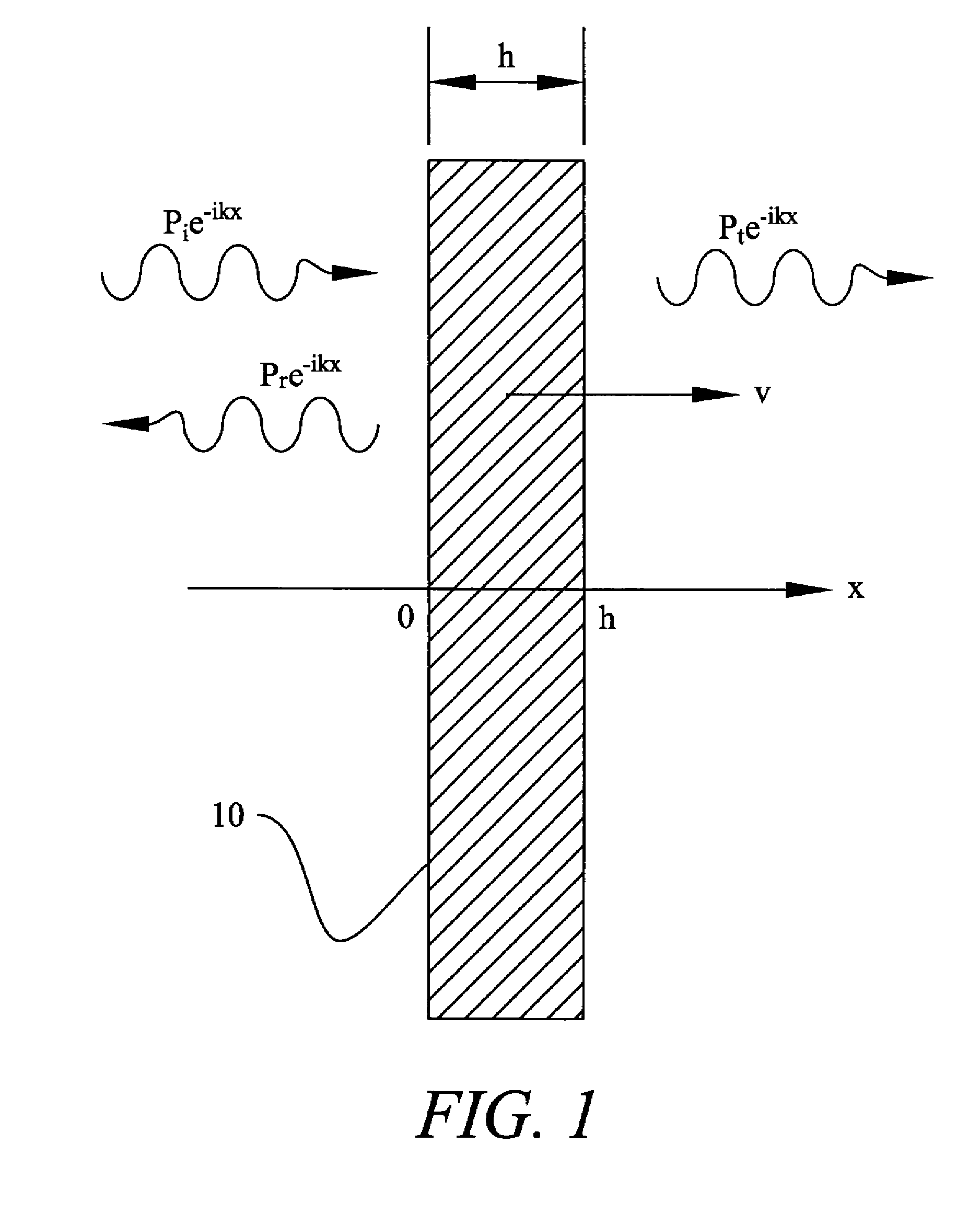
[0024]Referring now to FIG. 1, consider a thin plate (or membrane) of thickness h, insonified by an acoustic plane wave of amplitude Pi as seen in FIG. 1, with reflected and transmitted amplitudes, Pr and Pt, respectively. The plate is thin relative to the incident acoustic wavelength, that is, kh<<1, where k is the acoustic wave number, and the harmonic time dependency is ignored. Given this, the plate's velocity can be assumed constant thr...


PUM


Abstract

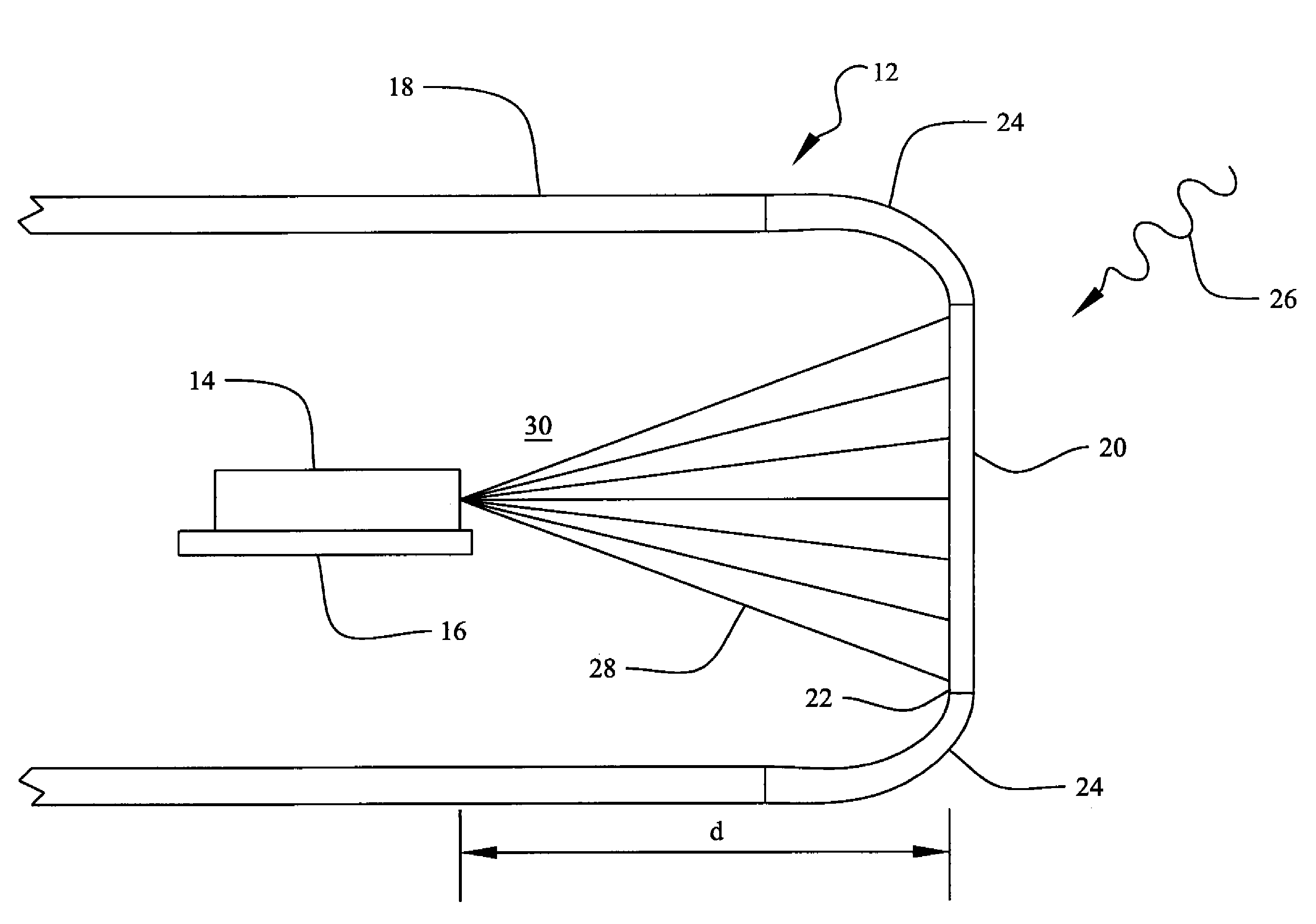
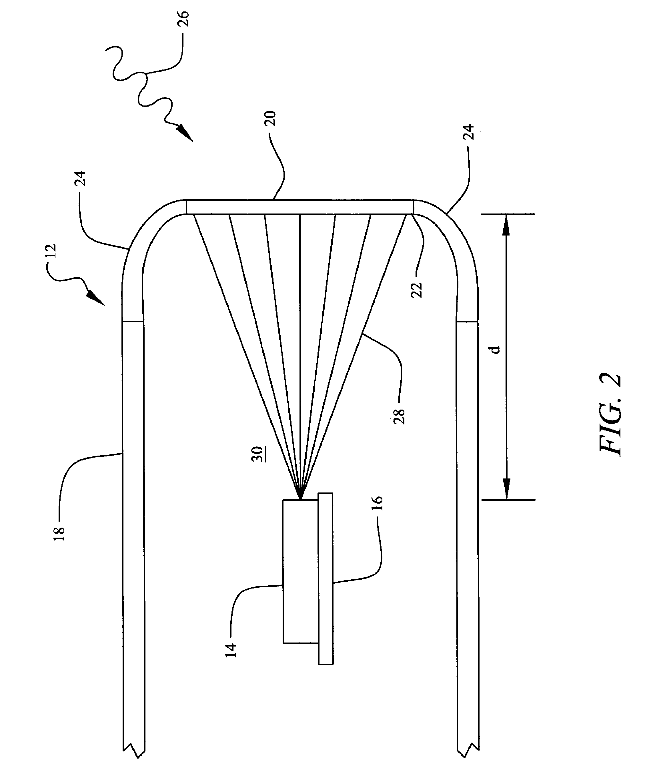
An acoustic sensing device includes a housing having an internal cavity filled with a vibration decoupling medium. An acoustic window formed of an acoustically transparent material is mounted in the housing. This mounting can be by antivibration mounts to prevent housing noise from affecting the acoustic window. A scanning laser vibrometer is positioned within the housing and directed to detect vibrations of the acoustic window. Antivibration mounts are joined between said scanning laser vibrometer and said housing. In further embodiments, the scanning laser vibrometer detects vibrations at a plurality of locations on the acoustic window forming a virtual array.

Description

STATEMENT OF GOVERNMENT INTEREST[0001]The invention described herein may be manufactured and used by or for the Government of the United States of America for Governmental purposes without the payment of any royalties thereon or therefore.CROSS-REFERENCE TO RELATED PATENT APPLICATIONS[0002]None.BACKGROUND OF THE INVENTION[0003](1) Field of the Invention[0004]The present invention relates generally to acoustic sensors, and in particular to a laser vibrometer acoustic sensor for use in underwater applications.[0005](2) Description of the Prior Art[0006]Sonar systems traditionally use an array of pressure-sensing hydrophones to detect underwater sound. The individual hydrophones (or array elements) are configured in a linear, planar, or conformal grid and then the output voltage from each hydrophone is summed. Fundamentally, the hydrophone converts the underwater acoustic pressure to a calibrated voltage. Array sampling theory requires that the separation between the array elements be ...

Claims


Application Information

Patent Timeline
Patent Type & Authority Patents(United States)
IPC IPC(8): H04R1/44
CPCH04B11/00H04B10/1121
Inventor CRAY, BENJAMIN A.BOOBER, WALTER H.FORSYTHE, STEPHEN E.ESTES, LEE E.HULL, ANDREW J.
Owner COUNSEL THE UNITED STATES OF AMERICA NAVAL UNDERSEA WARFARE CENT DIV NEWPORT OFFICE OF COUNSEL
Learn More