
Brightness control method and device for a display

a brightness control and display technology, applied in the field of planar displays, can solve the problems of affecting the brightness of the entire frame, and the human eye is insensitive to the poor frame quality produced by the reduction of brightness, so as to avoid the flicker of brightness, low system cost, and simple circuit design

Inactive Publication Date: 2009-11-03
SUNPLUS TECH CO LTD
View PDF5 Cites 13 Cited by
  • Summary
  • Abstract
  • Description
  • Claims
  • Application Information

AI Technical Summary

Benefits of technology

[0009]An object of the invention is to provide a brightness control method and device for a display, which can avoid a brightness flicker otherwise produced by frames with intermittent scenes.
[0010]A further object of the invention is to provide a brightness control method and device for a display, which does not use a frame buffer to store the entire frame and accordingly the circuit design is simple and the system cost is low.

Problems solved by technology

However, such products are only equipped with cells, which provide limited power.
Conversely, when most gray values of the frame are concentrated on the light image regions, the backlight brightness remains in the normal mode, such that human eyes are insensitive to the poor frame quality produced by the reduced brightness.
However, the method (A) directly affects the entire frame's brightness and can save power only at an idle mode.
In addition to calculating the brightness distribution statistics, the method (B) needs a frame buffer to store the entire frame, which makes the circuit design become relatively complex and increases the system cost.

Method used


Image

  • Brightness control method and device for a display
  • Brightness control method and device for a display
  • Brightness control method and device for a display

Examples


Embodiment Construction

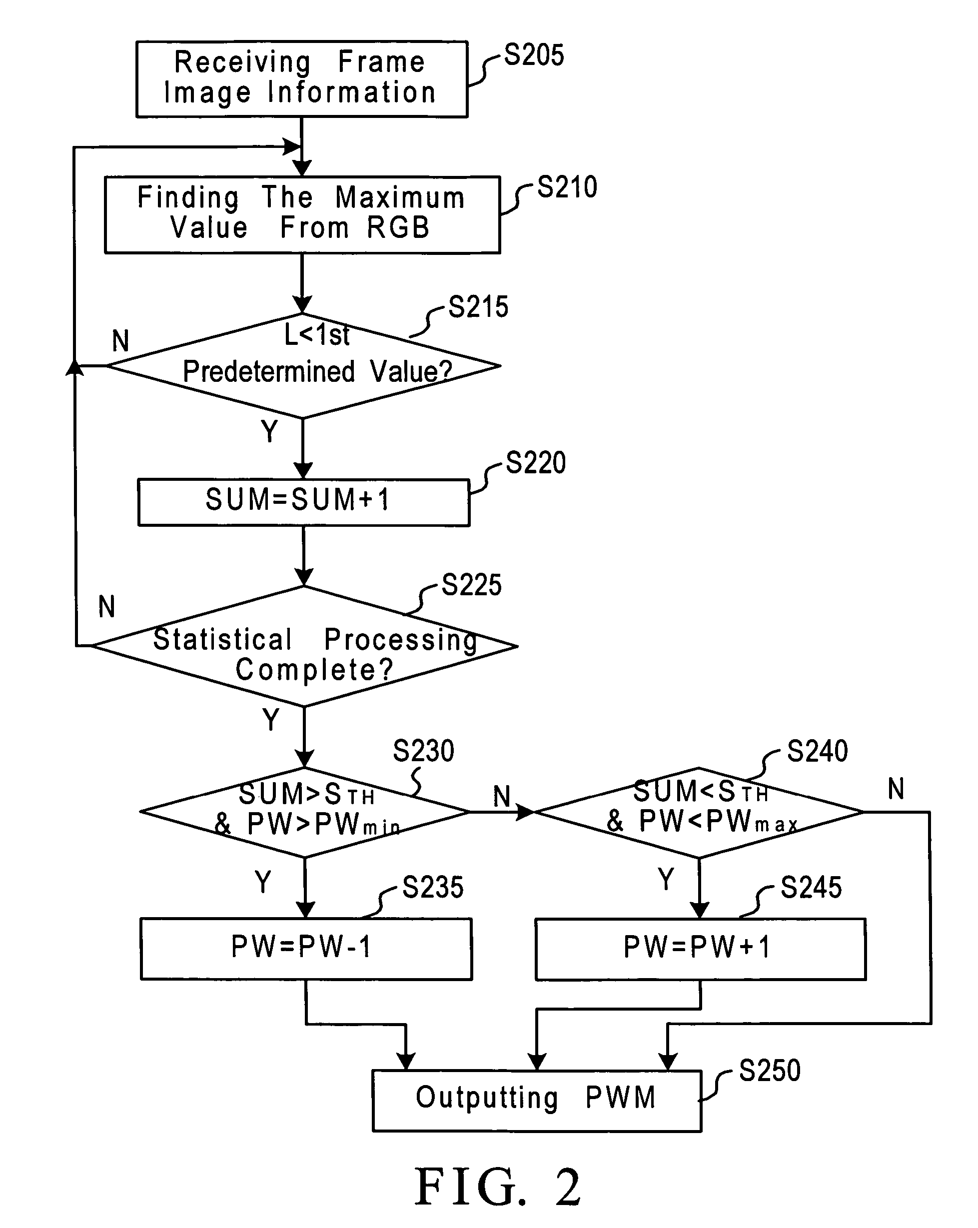
[0017]The invention is achieved by calculating a proportion of high light regions of partial image. Namely, if the number of pixels in high light parts of consecutive horizontal scan lines is smaller than a predetermined value, a backlight brightness is gradually reduced to thus save backlight power consumption.

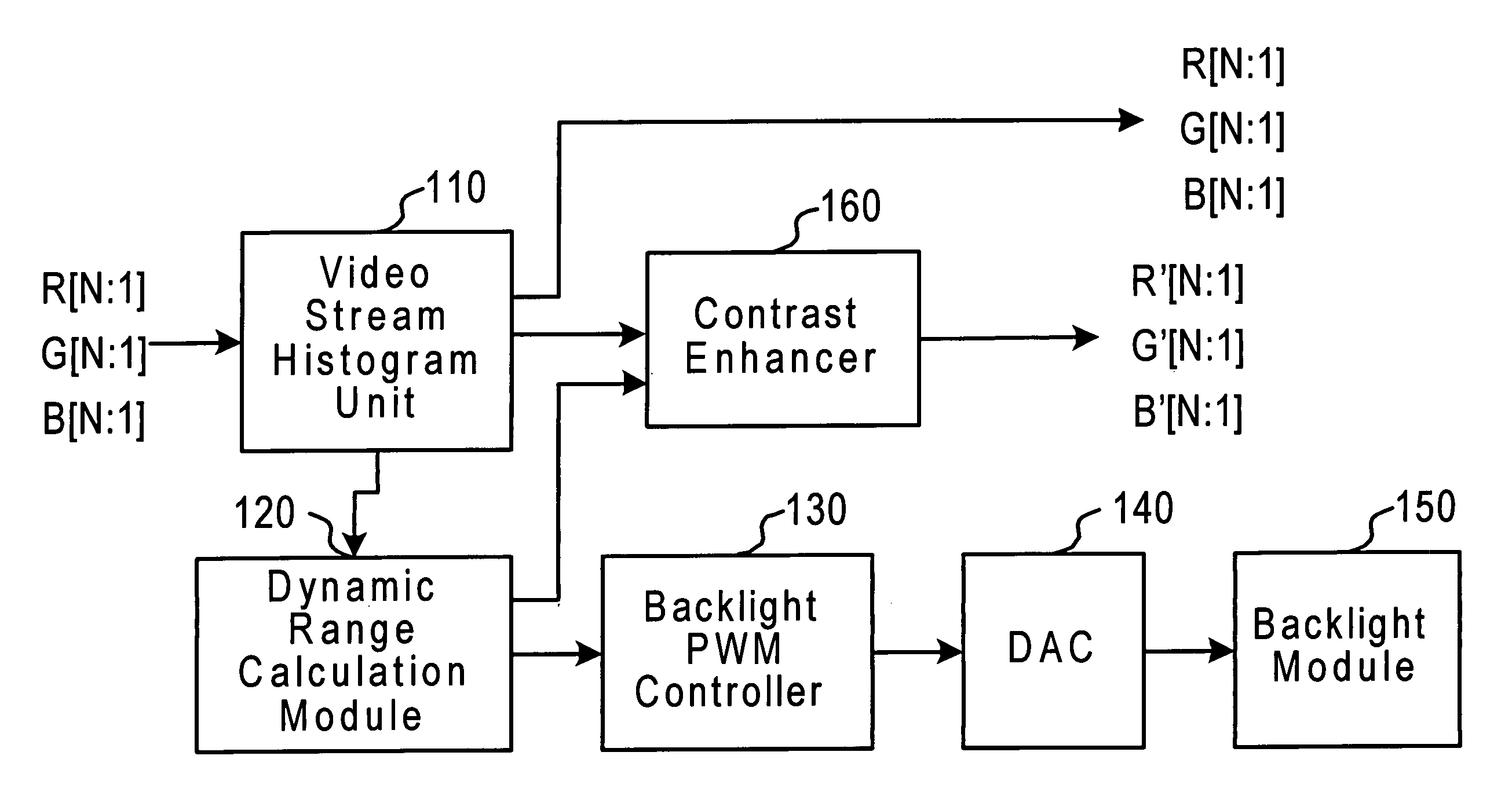
[0018]FIG. 1 is a block diagram of an embodiment of a brightness control device for a display in accordance with the invention. As shown, the device includes a video stream histogram unit 110, a dynamic range calculation module 120, a backlight pulse width modulation (PWM) controller 130, a digital to analog converter (DAC) 140, a backlight module 150 and a contrast enhancer 160.

[0019]As shown in FIG. 1, the video stream histogram unit 110 receives image information, i.e., RGB values, in order to perform statistical processing on partial frame, and thus finds a histogram from the partial frame that meets with the predetermined value. The dynamic range calculation module 120 r...


PUM


Abstract

A brightness control method and device for a display, which calculates a brightness distribution of partial frame image, determines when the partial frame image tends to be dark or light, compares a backlight brightness of the display with a predetermined value in accordance with the partial frame image determined, and accordingly adjusts the backlight brightness of the display.

Description

BACKGROUND OF THE INVENTION[0001]1. Field of the Invention[0002]The invention relates to the technical field of planar display and, more particularly, to a brightness control method and device for a display.[0003]2. Description of Related Art[0004]Currently, with the development of electronic technology, portable electronic products such as mobile phones, personal digital assistants (PDA), and MP3 players are getting more and more popular. Such products typically have a small screen with a panel. The panel can be a liquid crystal display (LCD), an organic light-emitting diode (OLED) or other typical planar displays. However, such products are only equipped with cells, which provide limited power. To overcome this drawback, these products typically adjust their displays to an appropriate brightness in order to increase the use time of an entire system.[0005]Typically, the current consumed by a planar display is increased with a higher brightness displayed on the display. For example,...

Claims


Application Information

Patent Timeline
Patent Type & Authority Patents(United States)
IPC IPC(8): G09G3/36
CPCG09G3/3406G09G2320/064G09G2320/0646G09G2360/16G09G2320/066G09G2330/021G09G2320/0653
Inventor YANG, HO-HSING
Owner SUNPLUS TECH CO LTD
Learn More