Reversed pressure relief valve

a pressure relief valve and reverse technology, applied in the direction of record information storage, rigid containers, food heating containers, etc., can solve the problem that the debris could negatively affect and achieve the effect of thin construction and negative impact on the operation of the disk drive mechanism

Active Publication Date: 2009-11-03
PLITEK
View PDF19 Cites 17 Cited by
  • Summary
  • Abstract
  • Description
  • Claims
  • Application Information

AI Technical Summary

Benefits of technology

[0003]Valves are used in connection with computer hard disk drives in conjunction with a normally venting valve. There is a need in the computer hard disk drive industry to have a one-way valve that vents gases out of the drive that allows the gas to be pressurized inside the valve. This vent valve allows ambient atmosphere to normalize and any moisture to pass out of the drive. It also blocks any foreign matter from returning.
[0005]The reversed valve for use with a disk drive is intended to operate such that normal (ambient) air pressure may be maintained within a chamber containing a hard disk drive while preventing debris from entering the disk drive chamber. The reversed valve is positioned over a hole in the disk drive chamber. The reversed valve permits air into the disk drive chamber. A filter media prevents debris from entering and contaminating the reversed valve assembly.
[0006]The present invention offers the advantage of having a relatively thin construction that is also extremely flexible. The present invention may operate under relatively low pressure since the valve closes mechanically once absolute pressure is obtained. The valve also maintains absolute pressure within the chamber without requiring any regulating mechanism.

Problems solved by technology

Debris could negatively impact the operation of the disk drive mechanism.

Method used


Image

  • Reversed pressure relief valve
  • Reversed pressure relief valve

Examples


Embodiment Construction

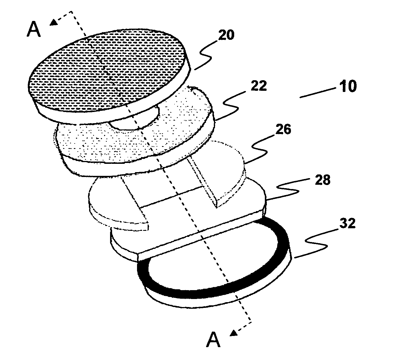
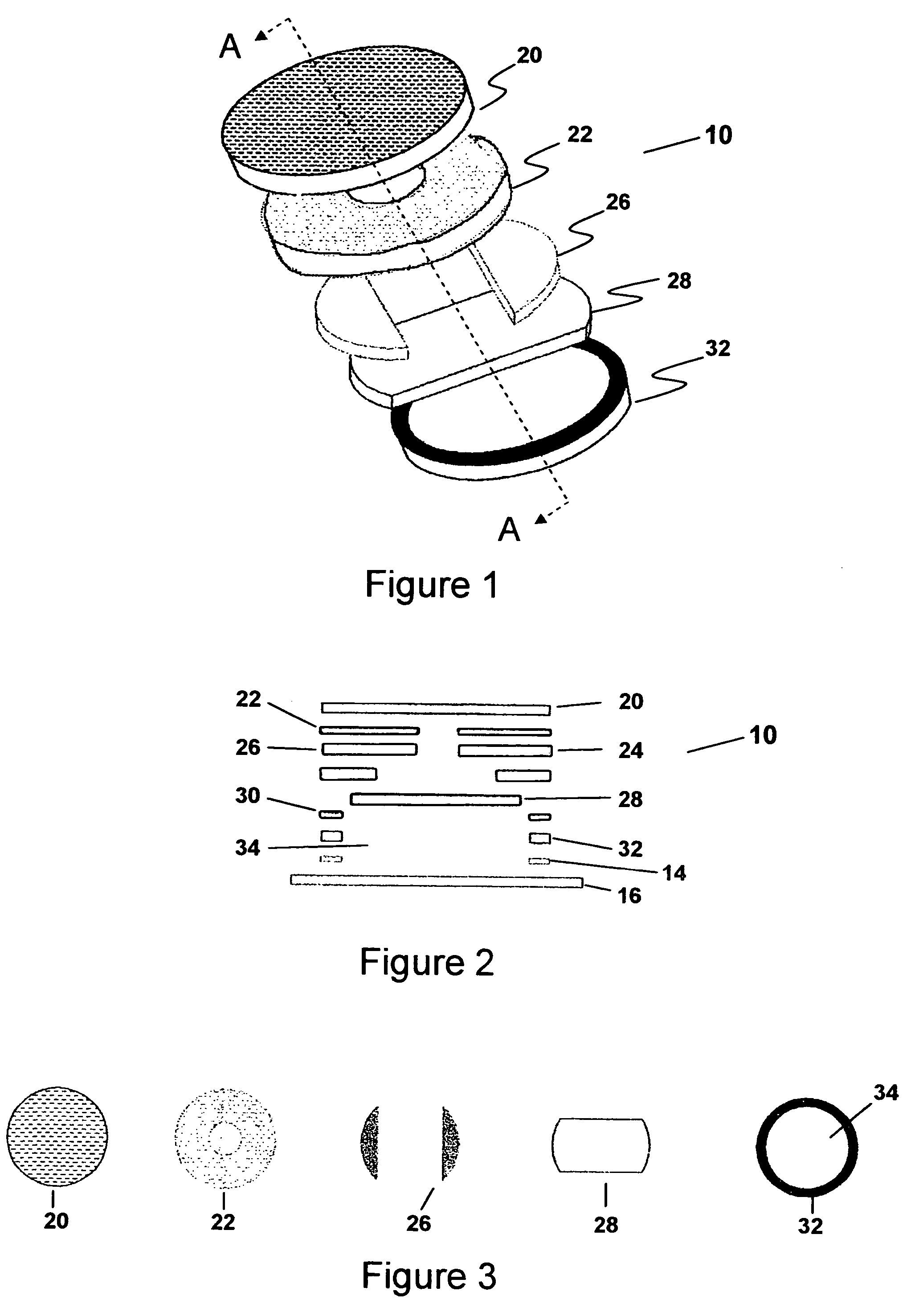
[0011]The construction of the reversed valve 10 is apparent from the depiction of the valve 10 in FIGS. 1-3. The filter media 20 is positioned at the uppermost portion of the valve 10. The filter media 20 may be constructed of non-woven media with or without a charcoal medium, but preferably is made of spun bond polypropylene. Typically, the filter media 20 is configured in a circular pattern, however, it could be constructed of other shapes as well.

[0012]Positioned below the filter media 20 is a laminating adhesive 22. The laminating adhesive 22 does not cover the entire surface area of the filter media 20. The laminating adhesive 22 adheres the filter media 20 to a pressure sensitive adhesive / body film 24. The laminating adhesive 22 is preferably a pressure sensitive material that complies with the minimal outgassing physical properties for adhesives in the market for hard disk drive products which are typically manufactured by companies like Avery Dennison, 3M, etc.

[0013]The PSA / ...


PUM

PropertyMeasurementUnit
sizeaaaaaaaaaa
thickaaaaaaaaaa
thickaaaaaaaaaa

Abstract

A reversed pressure relief valve that is used in connection with a computer hard disk drive so as to vent pressurized gases contained within the disk drive while not permitting debris to enter the drive mechanism or the valve. More specifically, the present invention is a reversed direction valve which includes at least one passageway defined by at least a lifter ring, a dry strap, a pressure sensitive adhesive (“PSA”) / body film and a filter media.

Description

BACKGROUND OF THE INVENTION[0001]The present invention relates to a reversed pressure relief valve that is used in connection with a computer hard disk drive so as to vent pressurized gases contained within the disk drive while not permitting debris to enter the drive mechanism or the valve. More specifically, the present invention is a reversed direction valve which includes at least one passageway defined by at least a lifter ring, a dry strap, a pressure sensitive adhesive (“PSA”) / body film and a filter media.SUMMARY OF THE INVENTION[0002]The invention pertains to a reversed valve that is used on packaging for and on computer hard disk drives. A typical pressure relief valve is enclosed within a chamber formed by walls and a filter membrane to vent products which produce an increased pressure within an enclosed space or chamber. To prevent excessive pressure from building within an enclosed chamber, a pressure relief valve is used to vent the gases causing a build-up of excessive...

Claims


Application Information

Patent Timeline
Patent Type & Authority Patents(United States)
IPC IPC(8): B01D53/04B01D53/22
CPCG11B33/1486G11B33/146
Inventor HOFFMAN, KARL K.
Owner PLITEK
Why Eureka
Try Eureka