
Image storage and display system, maintenance system therefor, and image storage and display method

a technology which is applied in the field of image storage and display system, maintenance system therefor, image storage and display method, can solve the problems of inability to confirm whether the setting is correct, inability to optimize parameters, and long initial adjustment time, so as to reduce time and optimize the compression ratio

Inactive Publication Date: 2009-10-13
TOSHIBA MEDICAL SYST CORP
View PDF19 Cites 4 Cited by
  • Summary
  • Abstract
  • Description
  • Claims
  • Application Information

AI Technical Summary

Benefits of technology

This system reduces the time and effort required for adjusting compression ratios, ensures optimal image quality and storage efficiency, and enables remote maintenance, improving the overall efficiency and usability of the image storage and display system.

Problems solved by technology

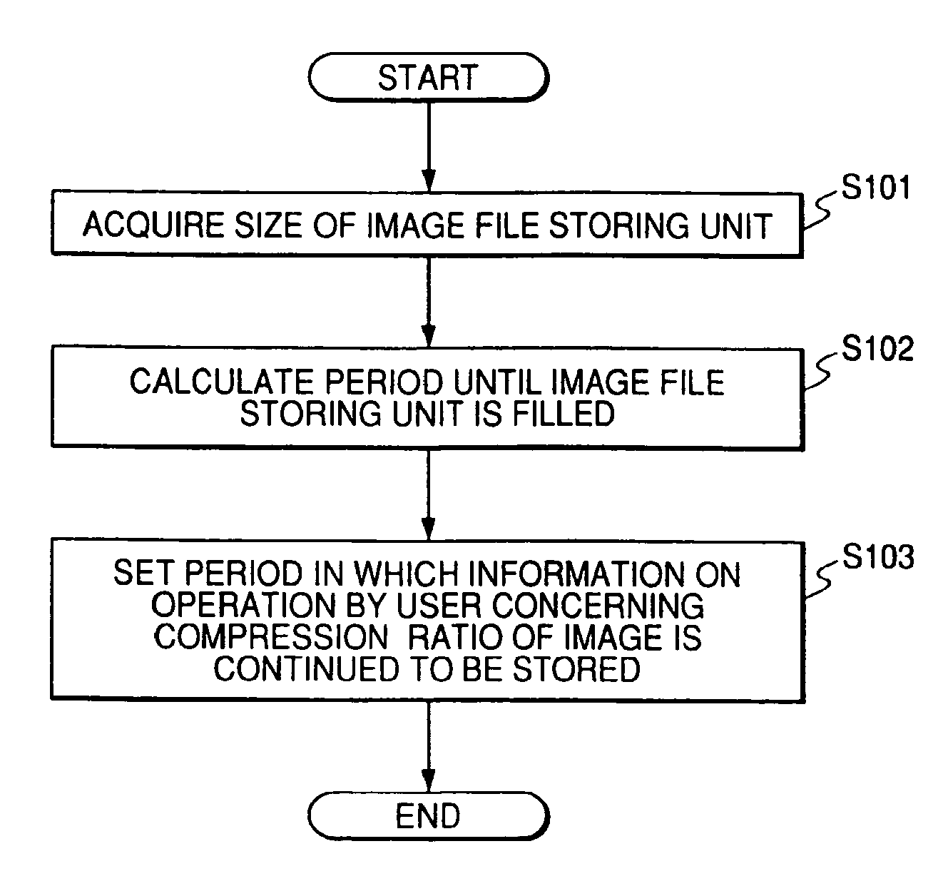
Thus, considerably long time is required for initial adjustment of parameters such as the compression ratio that affect a quality of images.
However, after the parameters such as the compression ratio are set at the time of system construction, it is impossible to confirm whether the setting is correct.
In addition, even if a change of the parameters is required in operation, since it is not clear according to what kind of standard and information the parameters should be changed, the parameters cannot be changed optimally.
For example, it is inefficient to store an image according to a compression method with a low compression ratio in order to give priority to a quality of the image, because a large storage area is required.
Conversely, if priority is given to efficiency of a storage, a user may be dissatisfied because an image quality is low.
However, this only makes it possible to select one of two kinds of images of different compression ratios but does not make it possible to designate a compression ratio.
Thus, it is still impossible to set an optimum compression ratio.

Method used


Image

  • Image storage and display system, maintenance system therefor, and image storage and display method
  • Image storage and display system, maintenance system therefor, and image storage and display method
  • Image storage and display system, maintenance system therefor, and image storage and display method

Examples


Embodiment Construction

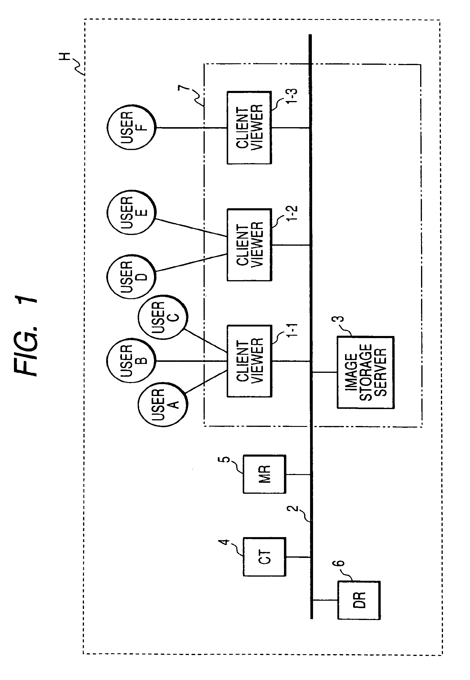
[0053]An image storage and display system according to a first embodiment of the invention will be explained with reference to the accompanying drawings. FIG. 1 schematically shows an entire image storage and display system 7 according to the first embodiment.

[0054]Client viewers 1 are installed in a medical facility site H. Only a single client viewer 1 may be installed in one medical facility H or plural client viewers 1-1, 1-2, 1-3, and the like may be installed as shown in the figure. For example, one client viewer 1-1 may be used by plural users A, B, C, and the like.

[0055]A local area network 2 is provided in the medical facility H. The client viewers 1 constitute a local area network (LAN) in conjunction with an image storage server 3, an X-ray computed tomographic (CT) apparatus 4, a magnetic resonance imaging (MR) apparatus 5, a digital radiography (DR) apparatus 6, and the like. Image files imaged by medical image generating apparatuses such as the CT apparatus 4, the MR a...


PUM


Abstract

The invention provides an image storage and display system including: an image storage server that includes an image file storing unit for storing image data; and image display terminals that are connected to the image storage server via a network and display an image sent from the image storage server. In the image storage and display system, the image storage server includes: an information managing unit that acquires and manages information on a system including at least one of environmental information and operation information of the system; and an image file compressing unit that sets an optimum compression ratio on the basis of the information to compress the image and stores the image in the image file storing unit. According to the constitution, it is possible to reduce time for, for example, adjustment of a compression ratio of an image by a user or a service person by automatically optimizing the compression ratio.

Description

BACKGROUND OF THE INVENTION[0001]1. Field of the Invention[0002]The present invention relates to an image storage and display system including an image server, which stores image data, and a display terminal, which is connected to the image server via a network, and an image storage and display method that is executed by the image storage and display system. The invention also relates to a maintenance system that maintains such an image storage and display system with remote control.[0003]2. Description of the Related Art[0004]In the medical field, various diagnostic image generating apparatuses (modalities) using an X-ray computed tomographic (CT) apparatus, an X-ray Digital Radiography (DR) apparatus, and a magnetic resonance imaging (MRI) apparatus, an ultrasonic diagnostic apparatus, and the like are used. Image data generated by these modalities are displayed on display devices such as CRTs and LCDs and used for various diagnoses in medical sites.[0005]In accordance with advanc...

Claims


Application Information

Patent Timeline
Patent Type & Authority Patents(United States)
IPC IPC(8): G06K9/00G06F15/16G06K9/36G06K9/46G06K9/54G06K9/60H04N11/02H04N11/04H04N7/12H04N7/16H04N7/173A61B6/00G06F12/00H04N1/21H04N1/413H04N7/24H04N7/26H04N7/30
CPCH04N21/234363H04N21/4667H04N21/6377H04N21/658H04N19/162H04N19/115H04N19/60H04N19/12H04N19/63
Inventor NIWA, KENICHIKONDO, TAKASHI
Owner TOSHIBA MEDICAL SYST CORP
Learn More