
Simplified power system for a cabin services system for an aircraft

a technology for aircraft cabin services and power systems, applied in the direction of aircraft crew accommodation, connection contact material, coupling device connections, etc., can solve the problems of occupying valuable space, complex wiring system, and requiring a large amount of skilled labor to perform the tedious and demanding installation of the cabin services system, so as to reduce noise and facilitate installation and maintenance.

Active Publication Date: 2009-10-06
THE BOEING CO
View PDF21 Cites 27 Cited by
  • Summary
  • Abstract
  • Description
  • Claims
  • Application Information

AI Technical Summary

Benefits of technology

[0010]A system and method in accordance with the present invention provides for the following features and advantages: (1) a passenger service unit power rail is integrated with the passenger service unit mounting rail to provide electrical power to the passenger service unit; and (2) individual personal air outlets are installed in the passenger service unit to eliminate ducting of a personal air outlet system, flex hose hookup, and to reduce noise. As a result of these features, a passenger service unit can be quickly installed and maintained without any wire, duct or tube hookups.

Problems solved by technology

Not only is this wiring system complex, but it also adds substantial weight to an aircraft and occupies valuable space.
In addition to wiring complexity, the amount of skilled labor to perform the tedious and demanding installation of the cabin services system—including the ducting for the gasper nozzles—is substantial.
In addition to the burden and complexity of the installation, other factors come into play when designing a passenger services system.
In this regard, the controls for conventional passenger services may often be difficult to reach, particularly for passengers with a seat belt fastened.
An in-flight entertainment system is generally heavy and is time consuming to install.
In addition, in-flight entertainment systems are typically complex, highly variable, and generate significant heat.
A portion of the in-flight entertainment system development cost involves work to meet cabin services system interfacing requirements.
This ducting takes up substantial space in the overhead area and requires a flex hose hookup to each passenger service unit upon installation which can be a physically tedious and demanding process for an airline mechanic.

Method used


Image

  • Simplified power system for a cabin services system for an aircraft
  • Simplified power system for a cabin services system for an aircraft
  • Simplified power system for a cabin services system for an aircraft

Examples


Embodiment Construction

[0023]The following description is presented to enable one of ordinary skill in the art to make and use the embodiments of the invention, and is provided in the context of a patent application and its requirements. Various modifications to the embodiments, generic principles, and features described herein will be readily apparent to those skilled in the art. Thus, the present invention is not intended to be limited to the embodiments shown, but is to be accorded the widest scope consistent with the principles and features described herein.

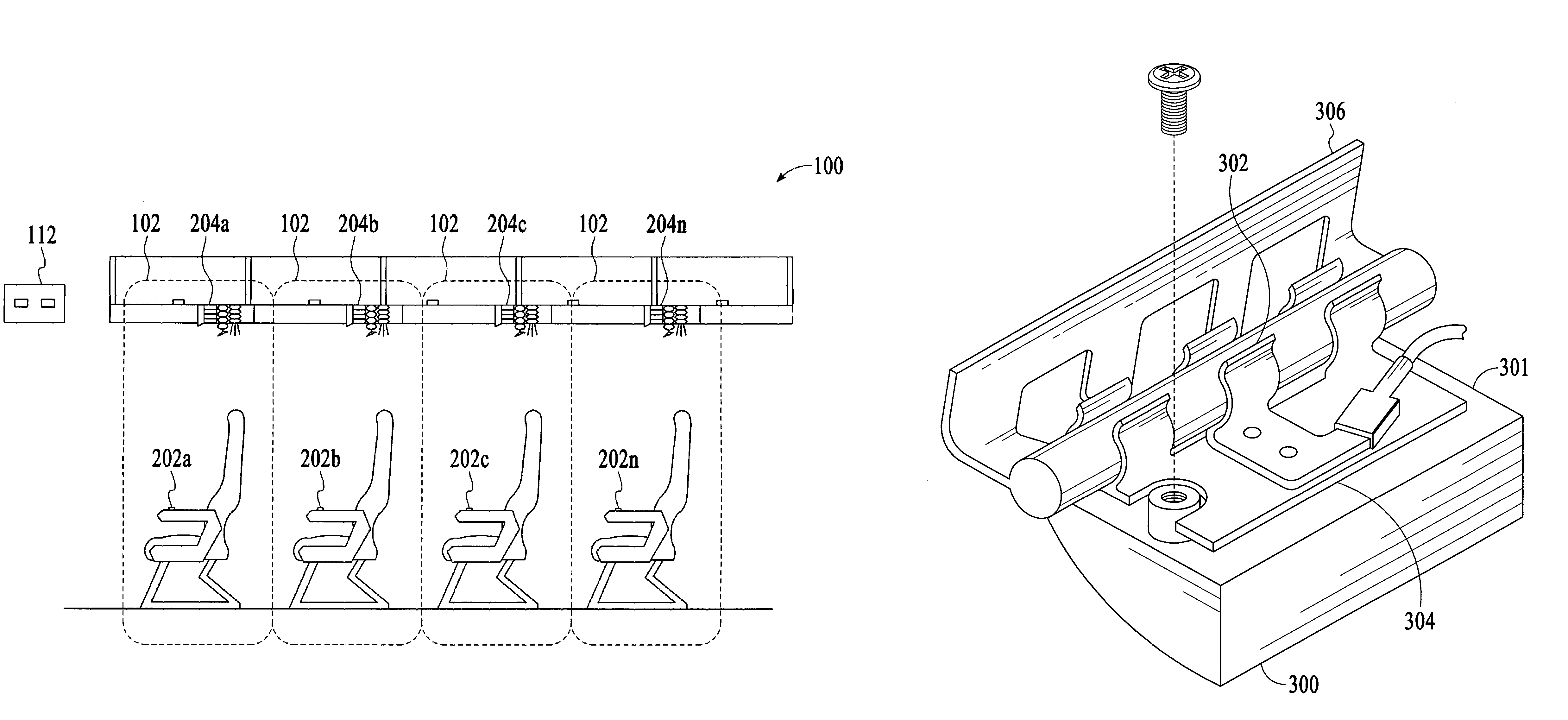
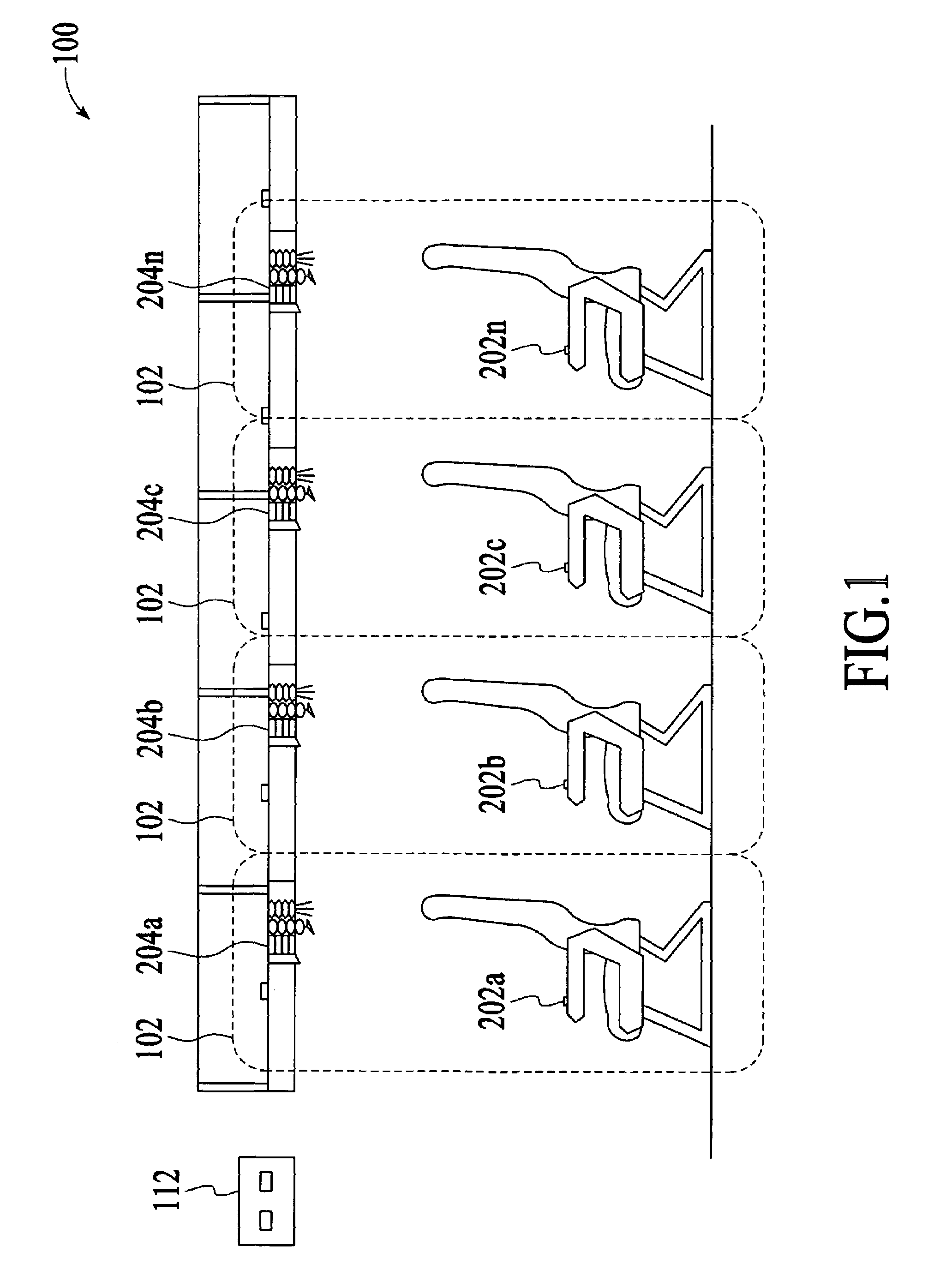
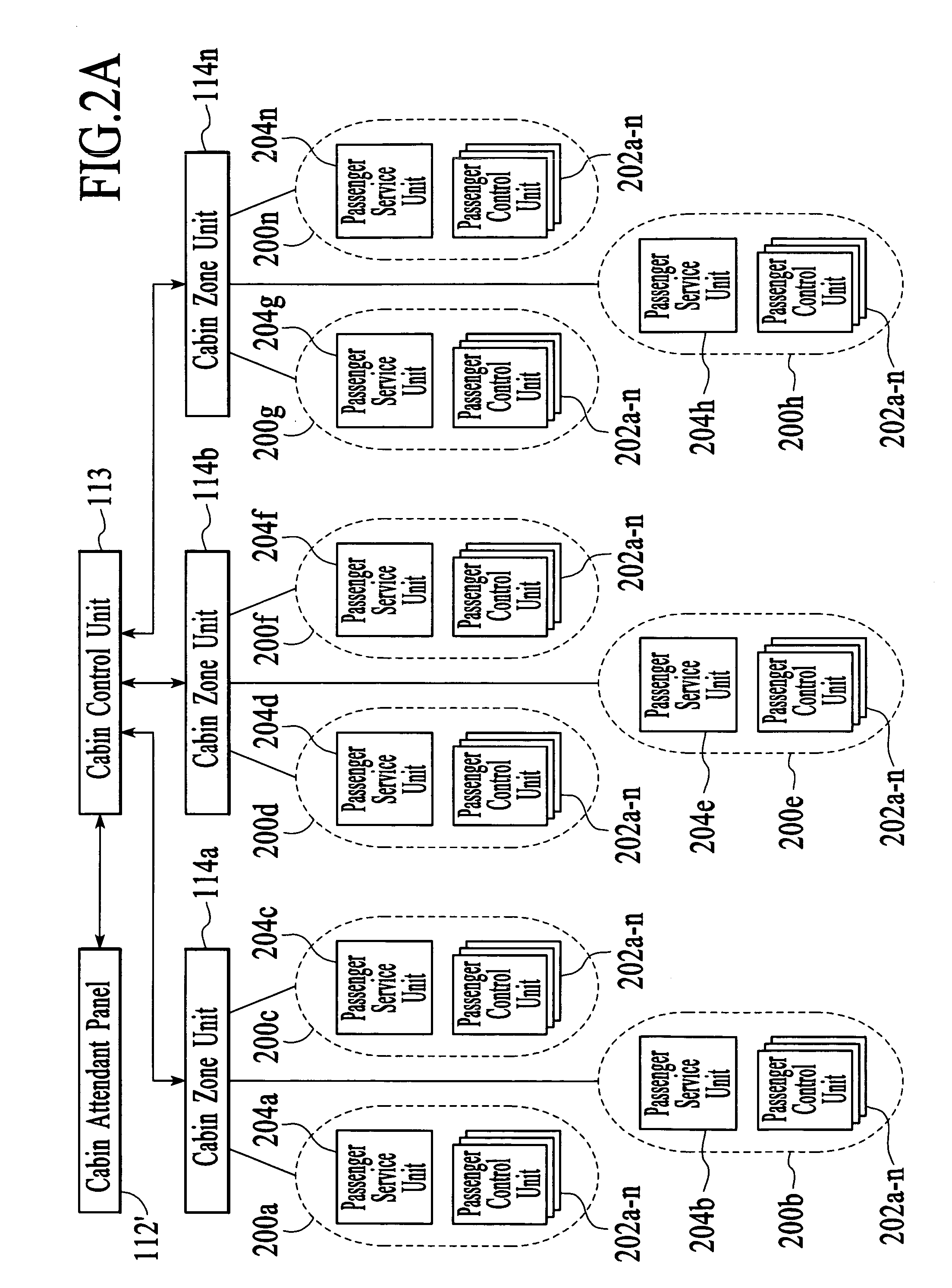
[0024]A cabin services system 100 according to a number of embodiments is illustrated in FIG. 1. The cabin services system 100 may include a plurality of wireless networks 102. Each of the wireless networks 102 may transmit and receive passenger services commands. Each of the wireless networks 102 may be preferably associated with a seat group. The cabin services system 100 may further include wireless passenger control units 202a-202n, passenger s...


PUM


Abstract

A mounting rail system for a cabin services system of an aircraft is disclosed. The mounting rail system comprises a mounting rail for providing power, and at least one circuit coupled to the mounting rail for allowing for operation of functionalities of a passenger services unit.

Description

FIELD OF THE INVENTION[0001]The present invention relates generally to commercial aircraft and more particularly to a simplified power system for a cabin services system in an aircraft.BACKGROUND OF THE INVENTION[0002]Commercial aircraft utilize a cabin services system to provide passengers with a number of services. Some of the cabin services address basic needs of the passengers, including air vents (known as “gasper nozzles”), reading lights, attendant-calling functions, emergency oxygen, and signage (e.g., FASTEN SEAT BELTS and NO SMOKING). Other cabin services are designed to enhance the flight experience of the passenger, including in-flight entertainment such as music and video (with either flip-down or seatback screens) and Internet connectivity such as Connexion® by Boeing.[0003]The mechanical, electrical, and pneumatic components that are employed to provide cabin services are packaged together in passenger service units. Each of these service units includes a set of contr...

Claims


Application Information

Patent Timeline
Patent Type & Authority Patents(United States)
IPC IPC(8): B64D11/00H01R3/00
CPCH02G3/32H02G3/00B64D2221/00
Inventor CALLAHAN, KEVIN S.LAIB, TREVOR M.LAMOREE, BRET L.LEE, DONALD B.MITCHELL, BRADLEY J.SANFORD, WILLIAM C.
Owner THE BOEING CO
Learn More