
Vibration-absorbing coupler and portable brush cutter provided with the vibration-absorbing coupler

a brush cutter and vibration-absorbing coupler technology, which is applied in the direction of yielding coupling, shaft and bearing, agriculture tools and machines, etc., can solve the problems of reducing affecting the service life of the cutter, and increasing fatigue, so as to reduce the twisting angle (the magnitude of elastic deformation), reduce the effect of torsional vibration of the transmission shaft and preventing the torsion coil spring from being easily damaged

Inactive Publication Date: 2009-09-29
KIORITZ
View PDF10 Cites 7 Cited by
  • Summary
  • Abstract
  • Description
  • Claims
  • Application Information

AI Technical Summary

Benefits of technology

[0011]With a view to realize the aforementioned object, the vibration-absorbing coupler according to one aspect of the present invention includes a torsion coil spring, so that the rotation of the output shaft of a prime mover is enabled to transmit to a transmission shaft via the torsion coil spring and a torsional vibration of the transmission shaft is enabled to be absorbed by the torsion coil spring; and further includes a rotation-regulator for regulating the torsion coil spring so as to prevent the spring from twisting more than a predetermined angle.
[0017]In the case of the vibration-absorbing coupler according to the present invention which is constructed as described above, the torsional vibration of the transmission shaft that may be caused by the fluctuation of torque, by the fluctuation of rotational speed, by the fluctuation of load on the cutting blade, or by the spring back phenomenon on the occasion of accelerating or decelerating the engine can be absorbed by the torsion coil spring which is built therein. Additionally, the torsion coil spring is regulated by the rotation-regulator so as to prevent the torsion coil spring from twisting more than a predetermined angle. Therefore, it is possible not only to effectively suppress the torsional vibration of the transmission shaft (i.e., undesirable vibration that will be transmitted to an operator's hands) but also to minimize the twisting angle (the magnitude of elastic deformation) of the torsion coil spring as compared with the case where this rotation-regulator is not provided. As a result, it is possible to prevent the torsion coil spring from being easily damaged and to enhance the durability of the torsion coil spring.
[0018]Further, according to the portable brush cutter equipped with this vibration-absorbing coupler, it is possible to effectively suppress the undesirable vibration that may be transmitted to the operator's hands through the operating rod or the handle.

Problems solved by technology

The portable brush cutter 1′ constructed in this manner however is accompanied with a problem that, due to the fluctuation of torque, the fluctuation of rotational speed, and the fluctuation of load to be imposed on the cutting blade 4 on the occasion of accelerating or decelerating the engine, torsional vibration occurs at the transmission shaft 7.
This kind of vibration may not only lead to the deterioration of operating performance of the cutter and to the increase of fatigue but also may become a cause for a white finger disease especially when the operation of the cutter is continued for long hours.
Therefore, to take measures for suppressing this torsional vibration is now an important issue in the manufacture of this portable brush cutter.
However, these conventional measures to use a coupler formed of vibration proof rubber, a one-way clutch or a torsion coil spring for suppressing the torsional vibration are not fully effective, even though some degree of effects to suppress the torsional vibration can be obtained.
Specifically, when a coupler formed of vibration proof rubber is used, the coupler generally has poor durability.
This may result in the torsion coil spring becoming easily fractured and hence deteriorating the durability thereof.

Method used


Image

  • Vibration-absorbing coupler and portable brush cutter provided with the vibration-absorbing coupler
  • Vibration-absorbing coupler and portable brush cutter provided with the vibration-absorbing coupler
  • Vibration-absorbing coupler and portable brush cutter provided with the vibration-absorbing coupler

Examples


Embodiment Construction

[0027]Next, various embodiments of the vibration-absorbing coupler according to the present invention will be explained with reference to the drawings.

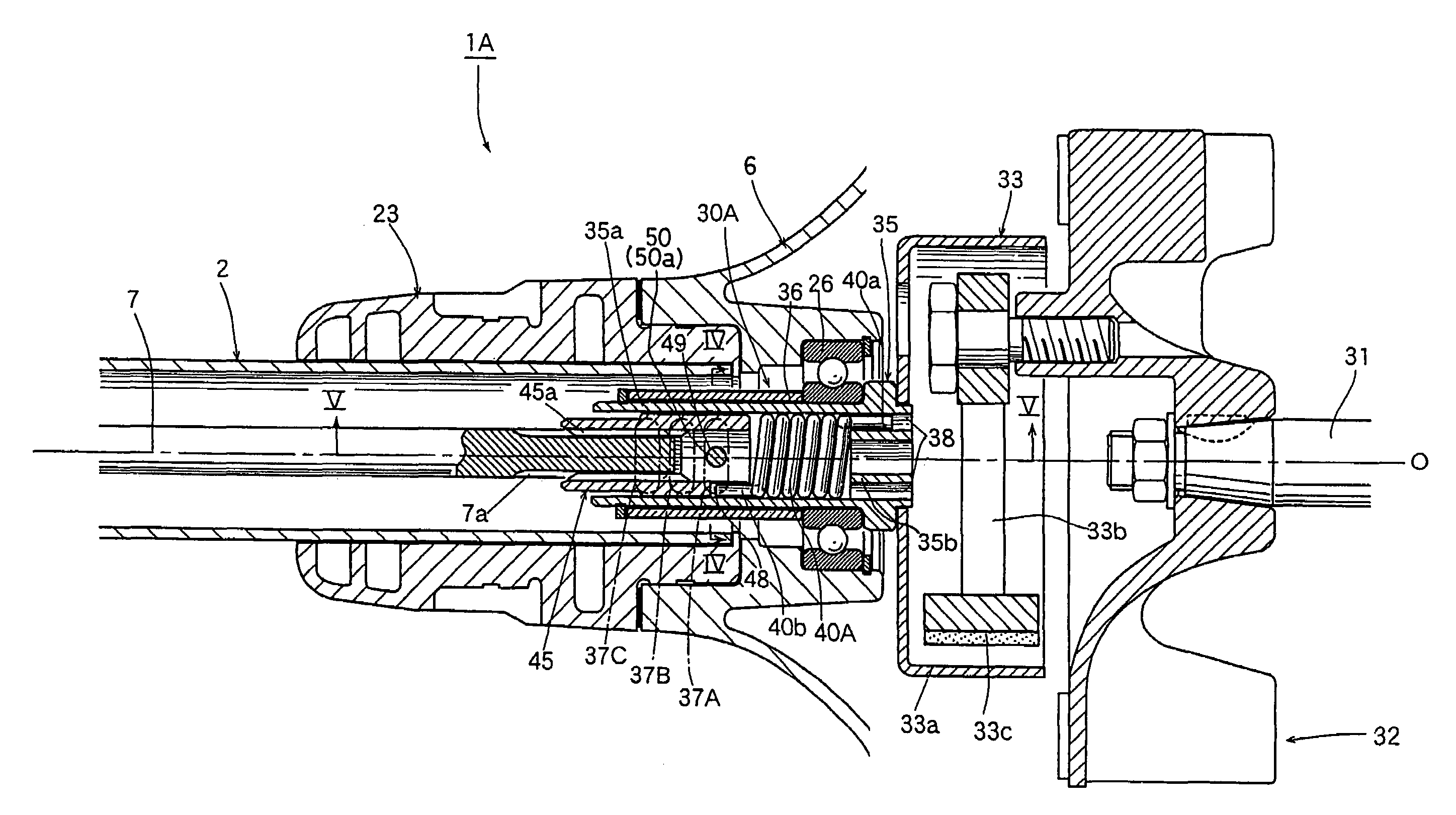
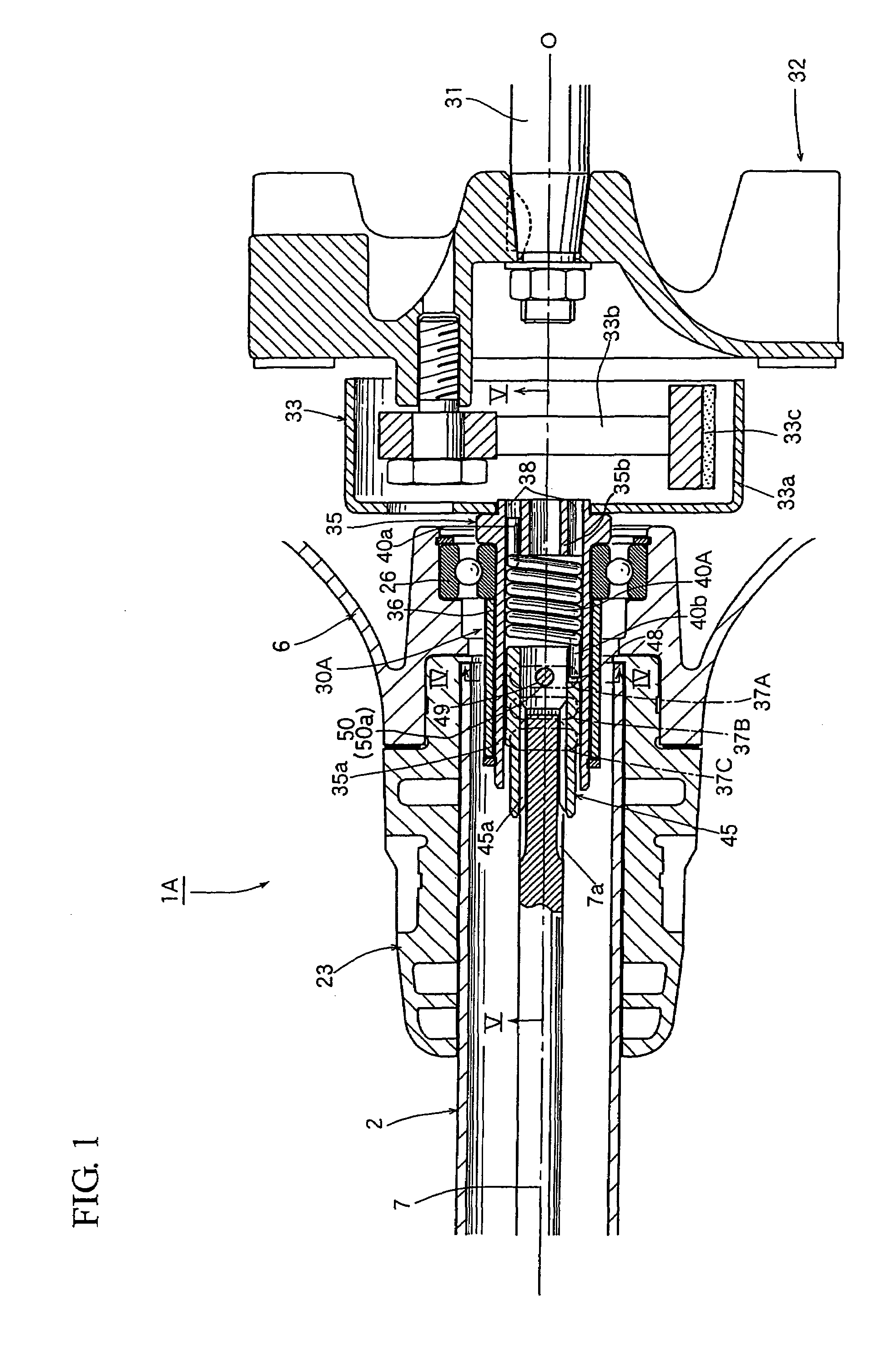
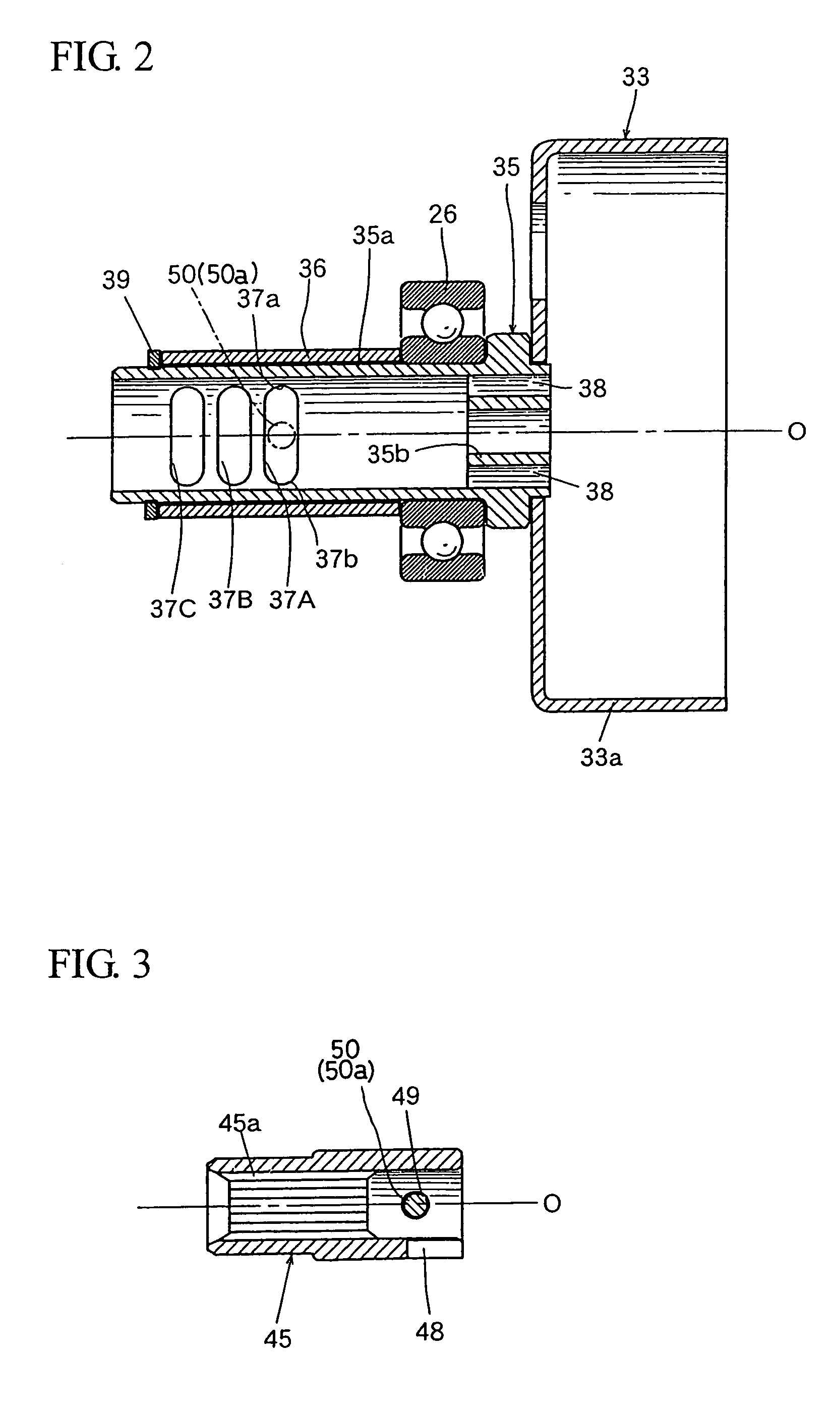
[0028]FIG. 1 is a cross-sectional view illustrating a main portion of a portable brush cutter with a vibrational-absorbing coupler according to one exemplary embodiment of the present invention.

[0029]The general structure of the portable brush cutter 1A shown in FIG. 1 is similar to that of the aforementioned portable brush cutter 1′ shown in FIG. 8. Namely, this portable brush cutter 1A is equipped, at a distal end of the operating rod 2 thereof, with a cutting blade mechanism 3 constituted by a cutting blade 4, a gear case 19, and other appropriate components. The brush cutter 1A is also equipped, at a proximal end of the operating rod 2 thereof, with a centrifugal clutch (33) attached internal combustion engine (an air cooling type small two-stroke cycle gasoline engine) 6 for driving the cutting blade 4 via a transmission shaft 7 ...


PUM


Abstract

A vibration-absorbing coupler (30A) which is capable of suppressing the torsional vibration of the transmission shaft (7) and also capable of enhancing the durability thereof is disclosed. This vibration-absorbing coupler (30A) is featured in that the rotation of an output shaft (31) of an internal combustion engine (6) is enabled to transmit to a transmission shaft (7) through a torsion coil spring (40A) and torsional vibration of the transmission shaft (7) is enabled to be absorbed by the torsion coil spring (40A). The vibration-absorbing coupler (30A) further includes a regulator (50, 37A) for regulating the rotation of the torsion coil spring (40A) so as not to allow it to twist more than a predetermined angle.

Description

FIELD[0001]The present invention relates to a vibration-absorbing coupler which is capable of transmitting the rotation of the output shaft of a prime mover to a transmission shaft and also capable of absorbing the torsional vibration of the transmission shaft. The present invention also relates to a portable brush cutter equipped with this vibration-absorbing coupler.BACKGROUND INFORMATION[0002]FIG. 8 shows one example of a conventional portable brush cutter. This portable brush cutter 1′ shown therein includes, at a distal end of the operating rod 2 thereof, a cutting blade mechanism 3 constituted by a cutting blade 4, a gear case (bevel gear unit) 19 and a safety cover 5. The portable brush cutter 1′ also includes, at a proximal end of the operating rod 2 thereof, a centrifugal clutch-attached internal combustion engine (an air cooling type small two-stroke cycle gasoline engine) 6 equipped with a recoil starter 8 and a fuel tank 9. This engine 6 acts as a prime mover for driving...

Claims


Application Information

Patent Timeline
Patent Type & Authority Patents(United States)
IPC IPC(8): B26B7/00
CPCA01D34/905
Inventor KOCHA, MASAHARU
Owner KIORITZ
Learn More