
Method and structure for suppressing response time of lens focusing structure

a technology of lens focusing and response time, which is applied in the direction of camera focusing arrangement, printers, instruments, etc., can solve the problems of inevitably jittering of auto-focusing camera lenses, suppress the dynamic response time of camera lenses, and improve camera focusing quality. , the effect of reducing the jitter

Active Publication Date: 2009-09-15
TDK TAIWAN
View PDF1 Cites 14 Cited by
  • Summary
  • Abstract
  • Description
  • Claims
  • Application Information

AI Technical Summary

Benefits of technology

[0007]A primary object of the present invention is to provide a method and structure for suppressing response time of lens focusing structure. With the method and structure, jitters produced by a camera lens when the same is displaced to a focused point, and then stopped may be absorbed, so as to suppress the dynamic response time of the camera lens to upgrade the camera focusing quality and reduce power consumed by the camera during focusing.
[0008]To achieve the above and other objects, the method of the present invention includes the step of forming between a movable mechanism and an immovable mechanism of a camera lens focusing structure with at least one receiving space for receiving at least one shock-absorbing element therein, such that the at least one shock-absorbing element is connected to and between the movable mechanism and the immovable mechanism to absorb jitters produced by the movable mechanism when the same is displaced to a focused point and then stopped, and thereby suppress the dynamic response time of the movable mechanism.
[0009]And, to achieve the above and other objects, the structure according to the present invention includes a movable mechanism, an immovable mechanism, and at least one shock-absorbing element. The movable mechanism has at least one base, which has a camera lens centered therein and a winding externally wound therearound. The immovable mechanism has at least a frame with magnetic members mounted to four sides thereof, a front cover, and a rear cover, and the movable mechanism is centered in the frame. The at least one shock-absorbing element is connected to and between the movable and the immovable mechanism for absorbing jitters produced by the movable mechanism when the latter is displaced to a focused point and then stopped, so as to suppress dynamic response time of the movable mechanism for going from a moving state back to a still state.
[0010]To achieve the above and other objects, the structure of the present invention further includes at least one elastic element, which includes a movable section connected to the movable mechanism and an immovable section connected to the immovable mechanism; and the at least one shock-absorbing element is connected to and between the movable section of the elastic element and the immovable mechanism, so as to absorb jitters produced by the movable mechanism when the latter is displaced to a focused point and then stopped, and thereby suppresses dynamic response time of the movable mechanism for going from a moving state back to a still state.

Problems solved by technology

An auto-focusing camera lens would inevitably jitter when the lens holder thereof is displaced to a focused point and then stopped.

Method used


Image

  • Method and structure for suppressing response time of lens focusing structure
  • Method and structure for suppressing response time of lens focusing structure
  • Method and structure for suppressing response time of lens focusing structure

Examples


Embodiment Construction

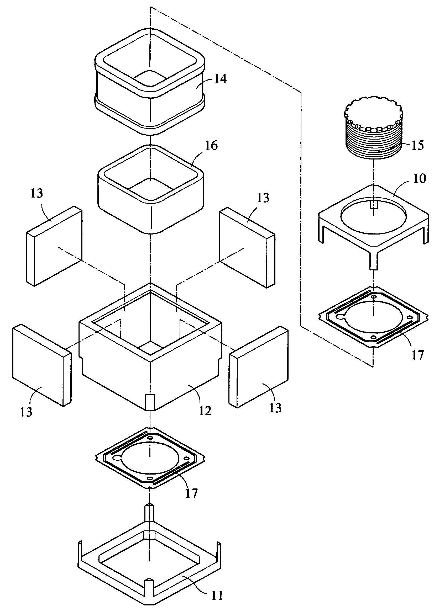
[0020]The present invention is designed to suppress the dynamic response time of a lens focusing structure, and will now be described in more details based on a camera lens focusing structure. Please refer to FIGS. 3 and 4A that are exploded and assembled perspective views, respectively, of a camera lens focusing structure 20 according to a preferred embodiment of the present invention, and to FIG. 4B that is an enlarged view of the circled area of FIG. 4A. As shown, the camera lens focusing structure 20 of the present invention includes a base 21, a plurality of magnetic members 23, a frame 24, a front cover 25, a rear cover 26, a housing 27, and a plurality of elastic elements 28. The base 21 includes a winding 30 externally wound therearound, and internally receives a centered lens 31. The base 21 is mounted and centered in the frame 24, and the magnetic members 23 are mounted to four sides of the frame 24 to locate around the winding 30 with a predetermined fixed distance left b...


PUM


Abstract

A lens focusing structure includes a movable mechanism having at least one base, which has a camera lens centered therein and a winding externally wound therearound; an immovable mechanism having at least a frame with magnetic members mounted to four sides thereof, a front cover, and a rear cover, and the movable mechanism being centered in the frame; and at least one shock-absorbing element connected to and between the movable and the immovable mechanism for absorbing jitters produced by the movable mechanism when the latter is displaced to a focused point and then stopped, so as to suppress dynamic response time of the movable mechanism for going from a moving state back to a still state.

Description

FIELD OF THE INVENTION[0001]The present invention relates to a method and structure for suppressing response time of lens focusing structure, and more particularly to a method and structure that is able to absorb jitters produced by a micro camera lens during focusing operation thereof, so as to suppress the dynamic response time of the lens and allow the lens to quickly go from a moving state back to a still state.BACKGROUND OF THE INVENTION[0002]Thanks to the advanced technologies and the modularized and miniaturized camera lenses, digital cameras may now have a largely reduced volume, and most of the currently available mobile phones may have a built-in digital camera to form the so-called camera phone. In the miniaturized camera lens module, an auto-focusing structure is provided. There are various types of auto-focusing structures for the modularized and miniaturized camera lens. Among others, a voice coil motor (VCM) has the advantages of small volume, low power consumption, a...

Claims


Application Information

Patent Timeline
Patent Type & Authority Patents(United States)
IPC IPC(8): G02B7/04G02B7/02G03B17/00
CPCG03B3/00
Inventor WU, FU-YUANFAN, CHAO-TING
Owner TDK TAIWAN
Learn More