Hydraulic tensioner

a technology of hydraulic tensioner and timing chain, which is applied in the direction of belt/chain/gearing, mechanical equipment, belts, etc., can solve the problems of increased production cost, increased production cost, and increased production cost, so as to achieve the optimal utilization of oil storage space, suppress the backlash of the timing chain, and prevent the generation of abnormal sounds

Active Publication Date: 2011-04-05
TSUBAKIMOTO CHAIN CO
View PDF12 Cites 15 Cited by
  • Summary
  • Abstract
  • Description
  • Claims
  • Application Information

AI Technical Summary

Benefits of technology

[0013]The bore within the plunger extends nearly the entire length of the plunger and can have a large diameter corresponding to the diameter of the plunger-receiving hole less twice the thickness of the wall of the plunger. As a result, the volume of the oil storage chamber formed by the bore in the plunger can be made sufficiently large to ensure an adequate supply of oil to the high pressure chamber of the tensioner. Thus, when the plunger is pushed into the plunger-accommodating hole, the supply of oil in the high pressure chamber is always sufficient to damp the movement of the plunger. Furthermore, when the plunger protrudes rapidly from the plunger-accommodating hole, causing the oil pressure in the high pressure chamber to drop, the oil in the high pressure oil chamber is replenished rapidly so that hydraulic damping can take place instantaneously when the plunger is again pushed into the plunger-accommodating hole. As a result, backlash of the timing chain is suppressed on engine start-up, and the generation of abnormal sounds is prevented.
[0014]Positioning the oil supply hole in the plunger on the ridge line of said plunger allows optimum utilization of the available oil storage space in the oil storage chamber inside the plunger.
[0015]The recess in the surface of the plunger maintains fluid communication between the oil supply bore in the tensioner housing and the oil supply hole in the plunger throughout the stroke of the plunger. Thus a reliable supply of oil is provided, through the housing, to the oil storage chamber inside the plunger. Additionally, the number of parts required in the tensioner is small compared to the number of parts in a tensioner utilizing a plunger sleeve, and the tensioner is comparatively easy to manufacture because difficult machining of the inside wall of the plunger-accommodating hole in the housing is unnecessary. When the length of the recess is sufficient that the oil supply bore is always in register with the recess throughout the stroke of the plunger, oil is always allowed to flow from the oil supply bore to the oil supply hole, ensuring an adequate supply of oil in the oil storage chamber inside the plunger. Furthermore, when the length of the recess is made is equal to the maximum stroke of the plunger, the overall length of the tensioner housing can be kept at a minimum.

Problems solved by technology

When a shock load acts on the front end of the plunger, leakage of oil from the high pressure chamber through a restricted clearance buffers the shock load.
The above-described hydraulic shock-absorbing tensioner has a greater number of parts than the usual conventional tensioner and a more complicated structure, since it includes a plunger sleeve and a sleeve spring fitted between the plunger housing and the plunger.
Moreover, even though the plunger is longer than a conventional plunger, the internal space available for storage of oil within the plunger is limited, and is inadequate under some conditions of operation where the demand for oil in the high pressure oil chamber is high.
In the above-described hydraulic shock-absorbing tensioner, the overlap of the mutually sliding surfaces of the plunger housing and the plunger is short, and consequently the leakage of oil through the restricted clearance between these mutually sliding surfaces can become excessive.
When the engine is not operated over an extended period of time, oil drainage from the oil reservoir and the high pressure chamber occurs as a result of leakage.
Then, when the engine is re-started, the hydraulic damping force exerted as a result of oil leakage cannot be realized until oil is restored in the oil reservoir and in the high pressure oil chamber.
As a result, troublesome backlash of the engine timing chain occurs on engine start-up, abnormal sounds are generated, and unexpected damage can occur.
Furthermore, when the plunger of the tensioner advances as a result of elongation of the timing chain, the backlash on engine start-up is exaggerated.
Similar exaggeration of backlash in the engine timing drive can occur when the tensioner is mounted so that the plunger protrudes upward at a small angle relative to the horizontal.

Method used


Image

  • Hydraulic tensioner
  • Hydraulic tensioner
  • Hydraulic tensioner

Examples


Embodiment Construction

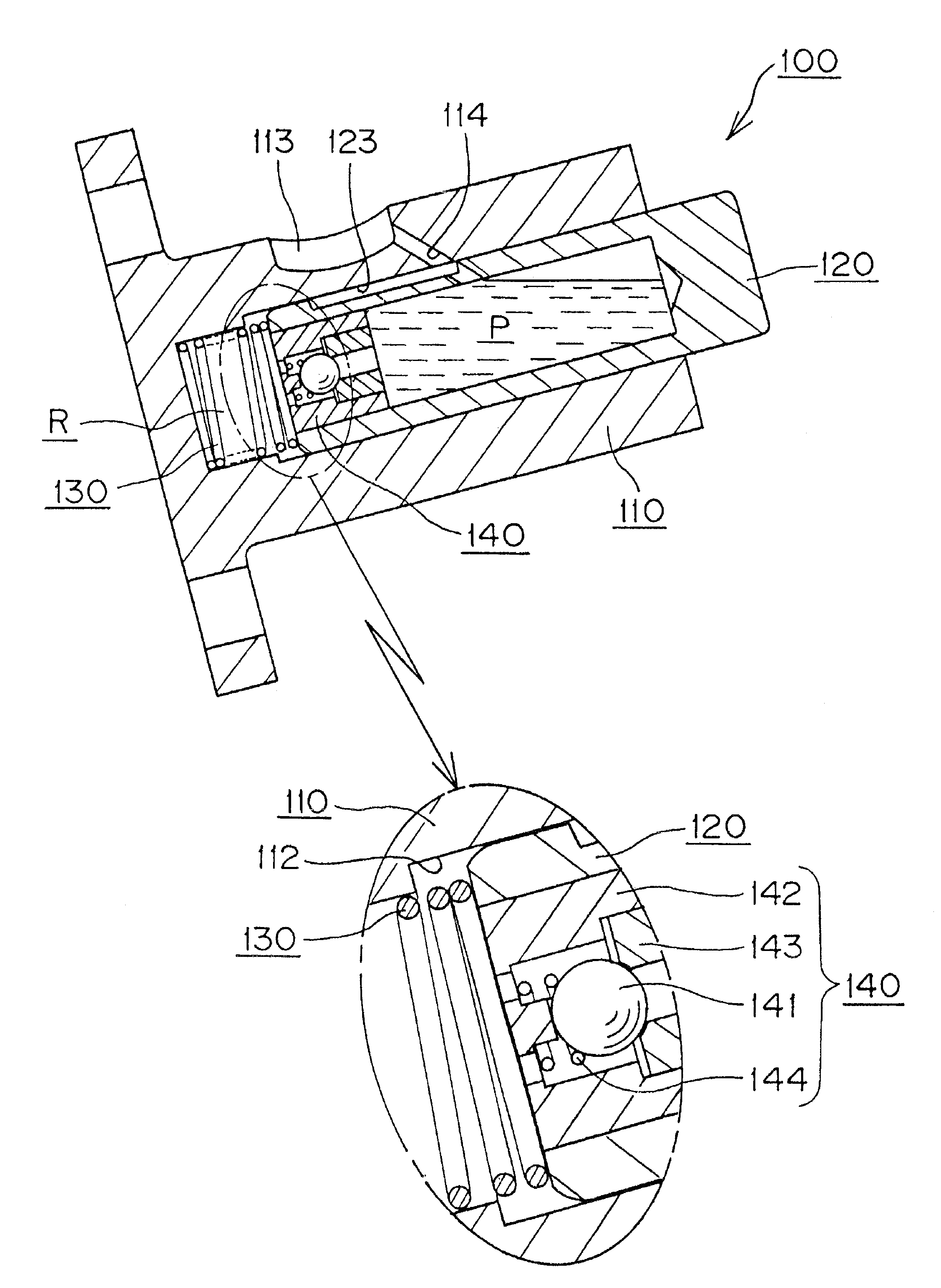
[0028]The invention will be described in the context of a ratchet-type hydraulic tensioner adapted for use with a pivoted chain guide or lever to maintain tension in the timing chain of a vehicle engine. However, the invention can be embodied in a tensioner wither with or without a ratchet mechanism, and also in a tensioner in which a chain guide is carried by a plunger.

[0029]The hydraulic tensioner of the invention is preferably attached in a vehicle engine in such a way that its plunger protrudes upward at an angle relative to the horizontal. However, the tensioner can be disposed so that its plunger protrudes horizontally or downward at an angle relative to the horizontal.

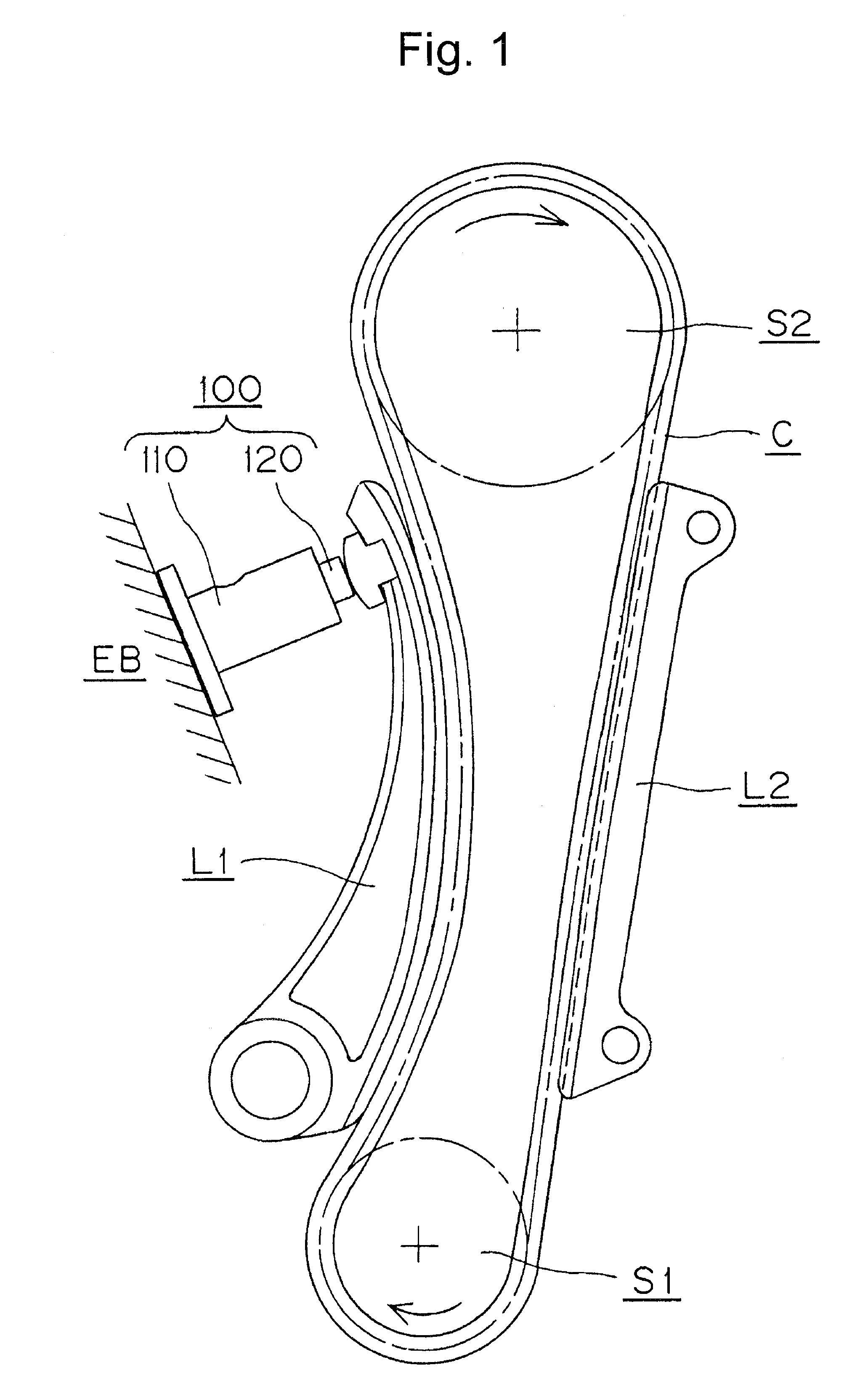
[0030]As shown in FIG. 1, a hydraulic tensioner 100, is attached to an engine body EB on the slack side of a timing chain C, which is extends from a crankshaft sprocket S1 to a camshaft sprocket S2. Arrows indicate the direction of rotation of the sprockets. A plunger 120 of the hydraulic tensioner 100 protrudes...


PUM


Abstract

A hydraulic tensioner comprises a plunger, and a plunger-accommodating hole in a tensioner housing, together forming a high pressure oil chamber. A plunger-biasing spring is provided in the high pressure oil chamber between the plunger and the bottom of the plunger-accommodating hole. An oil storage chamber is formed inside the plunger, and a check valve unit is press-fit in the rear end of the plunger to allow flow from the oil storage chamber to the high pressure oil chamber while blocking reverse flow of oil.

Description

CROSS-REFERENCE TO RELATED APPLICATION[0001]This application claims priority on the basis of Japanese patent application 2007-166839, filed Jun. 25, 2007. The disclosure of Japanese application 2007-166839 is hereby incorporated by reference.FIELD OF THE INVENTION[0002]This invention relates to hydraulic tensioners for maintaining proper tension in a timing chain such as a roller chain, a silent chain, or the like, in a vehicle engine. The invention relates more specifically to a hydraulic tensioner in which an oil storage chamber is formed within the plunger of the tensioner.BACKGROUND OF THE INVENTION[0003]Hydraulic tensioners comprising housings with protruding plungers have been used in vehicle engines for maintaining tension in timing chains that transmit rotation from an engine crankshaft to one or more valve-operating camshafts. The plunger usually engages a movable guide having a shoe on which a portion of the chain traveling away from a crankshaft sprocket slides. The plung...

Claims


Application Information

Patent Timeline
Patent Type & Authority Patents(United States)
IPC IPC(8): F16H7/22
CPCF16H7/0848F16H2007/0806F16H2007/0859F16H2007/0853F16H2007/0812F16H7/0836F16H7/08
Inventor KUREMATSU, YUGI
Owner TSUBAKIMOTO CHAIN CO
Why Eureka
Try Eureka