
Technique for coupling entities via virtual ports

a technology of virtual ports and entities, applied in the field of data networking, can solve the problems of blocking traffic on the other vlans, stp may not work properly, vcs may not appear transparent to various l2 protocols operated over the vlan, etc., and achieve the effect of consuming additional resources and conserving resources

Inactive Publication Date: 2009-09-08
CISCO TECH INC
View PDF12 Cites 57 Cited by
  • Summary
  • Abstract
  • Description
  • Claims
  • Application Information

AI Technical Summary

Benefits of technology

[0012]The present invention relates to a technique for efficiently transferring data between geographically dispersed entities belonging to a virtual-local-area network (VLAN). According to the technique, the geographically dispersed entities communicate via software-defined virtual ports that “appear” as physical ports to the entities. Each virtual port, in turn, is associated with one or more connections wherein each connection may be associated with a VLAN. Data generated on a particular VLAN that is destined for a remote entity is forwarded to a virtual port which, in turn, transfers the data to the remote entity over the connection associated with the VLAN. Moreover, state is maintained at each virtual port for each connection thereby enabling the virtual ports to support various protocols that operate with physical ports.
[0016]Advantageously, the inventive technique is an improvement over prior schemes in that the virtual port appears as a “physical” port and enables certain protocols that deal with physical ports to operate where they may not otherwise operate using the prior schemes, such as those that rely on logical communication links like VCs. Moreover, the inventive technique conserves resources in that it enables many connections (e.g., VCs) associated with various VLANs to be associated with a single virtual port. The virtual port in turn is associated with a single control structure. As a result, many connections may be associated with a single control structure, thereby obviating having to maintain a separate control structure for each connection and consequently consume additional resources.

Problems solved by technology

One problem with using VCs to carry VLAN traffic is that the VCs may not appear transparent to various L2 protocols operated over the VLAN.
Since only one BPDU is generated for the ATM port, the STP may not operate properly as there will not be enough BPDUs for transfer over all the VCs associated with the VLAN.
This may pose a problem with ATM implementations wherein a blocked VC blocks an entire ATM port.
For example, if the ATM port is associated with a plurality of VCs and each VC is associated with a different VLAN, blocking a VC to meet the requirements of the STP for a particular VLAN may inadvertently cause traffic on the other VLANs to be blocked as well.
Another problem associated with coupling VLANs via VCs is that in some intermediate nodes a separate control structure may be maintained for each VC.
Often, the number of control structures available in an intermediate node is limited due to limited resources available to the node, e.g., a limited amount of memory storage.
Consequently, if the number of dispersed entities in a VLAN is quite numerous and requires many VCs, an intermediate node in the network may not have sufficient resources to maintain control structures for all the VCs needed to couple the entities belonging to the VLAN.

Method used


Image

  • Technique for coupling entities via virtual ports
  • Technique for coupling entities via virtual ports
  • Technique for coupling entities via virtual ports

Examples


Embodiment Construction

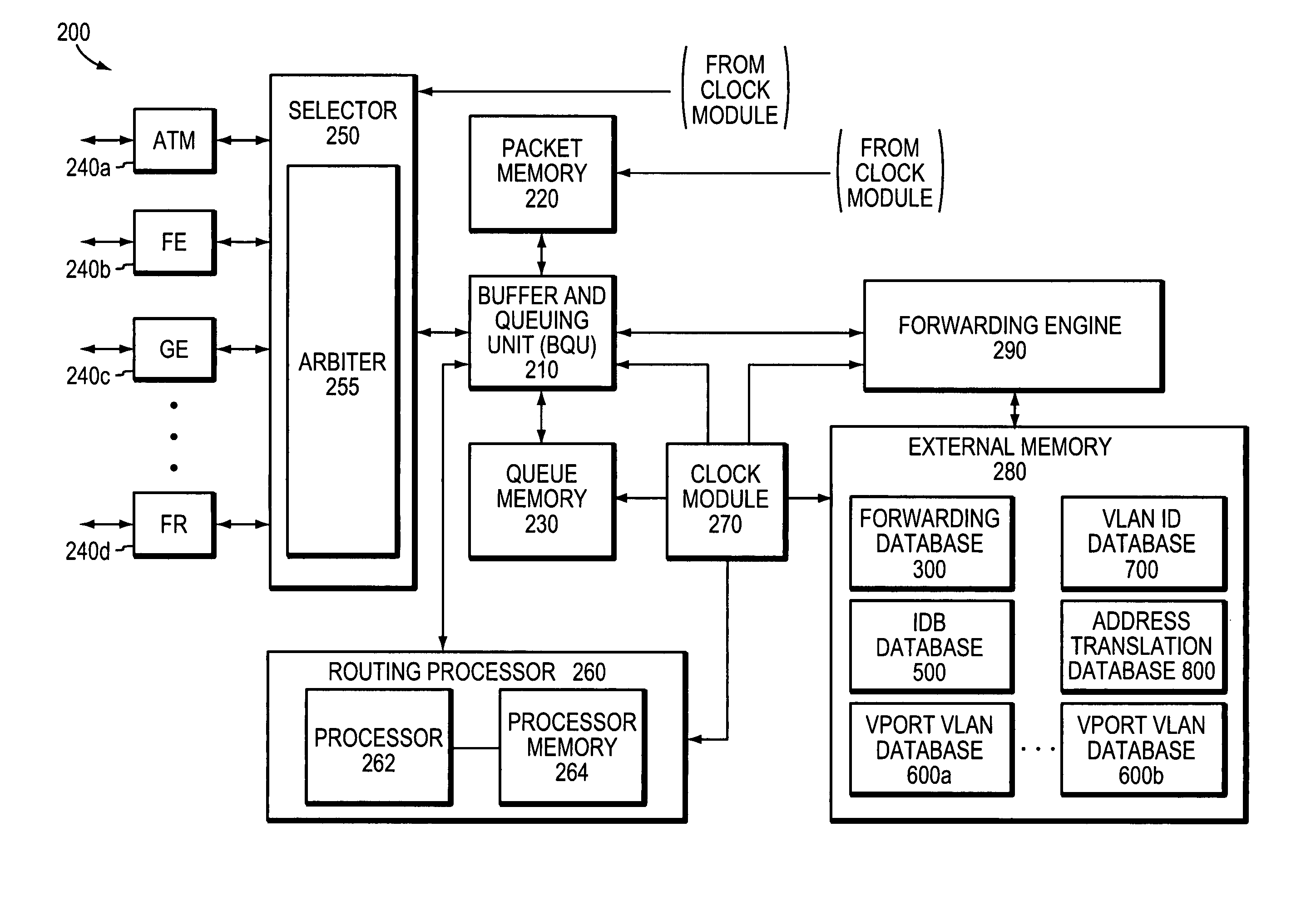
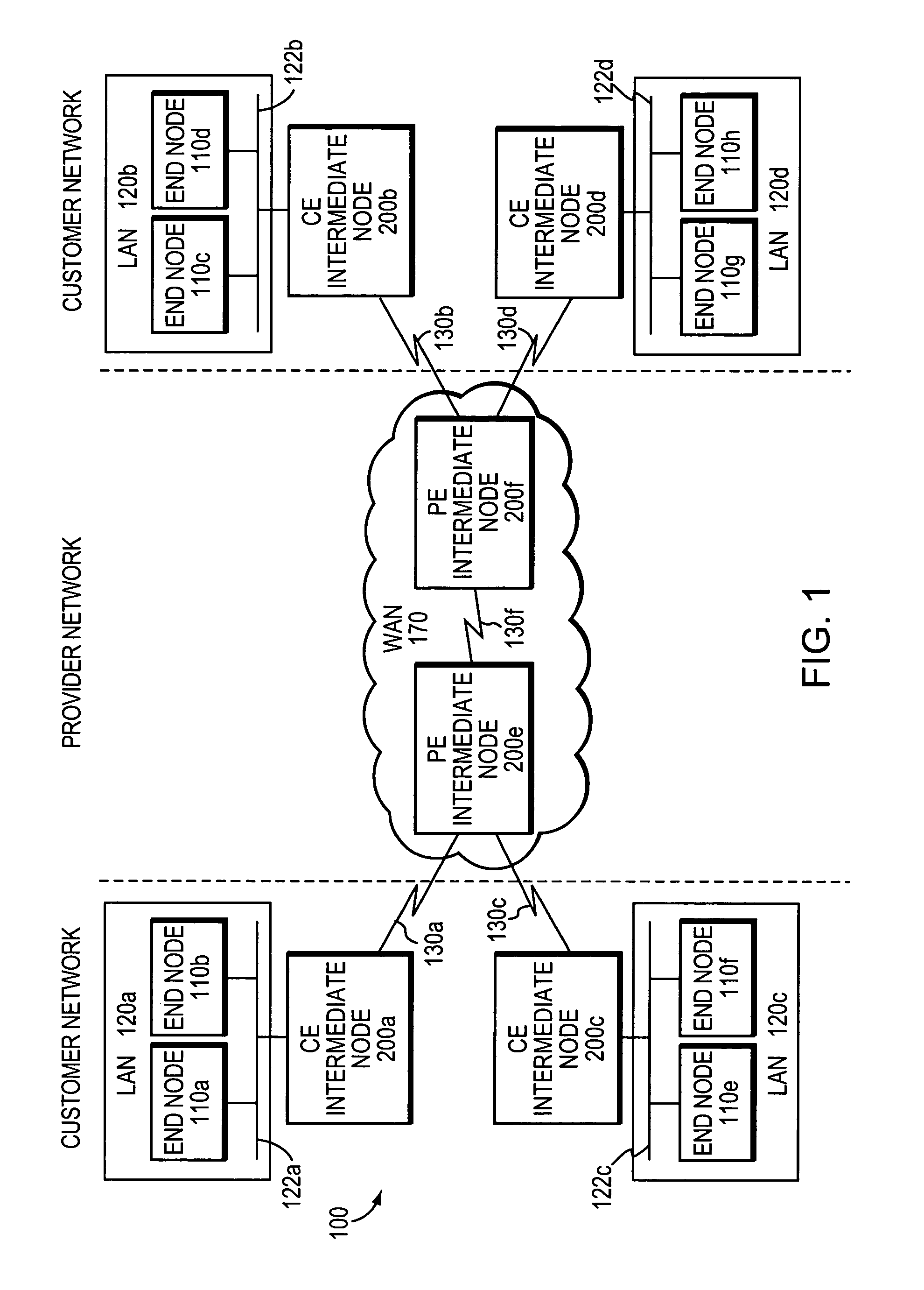
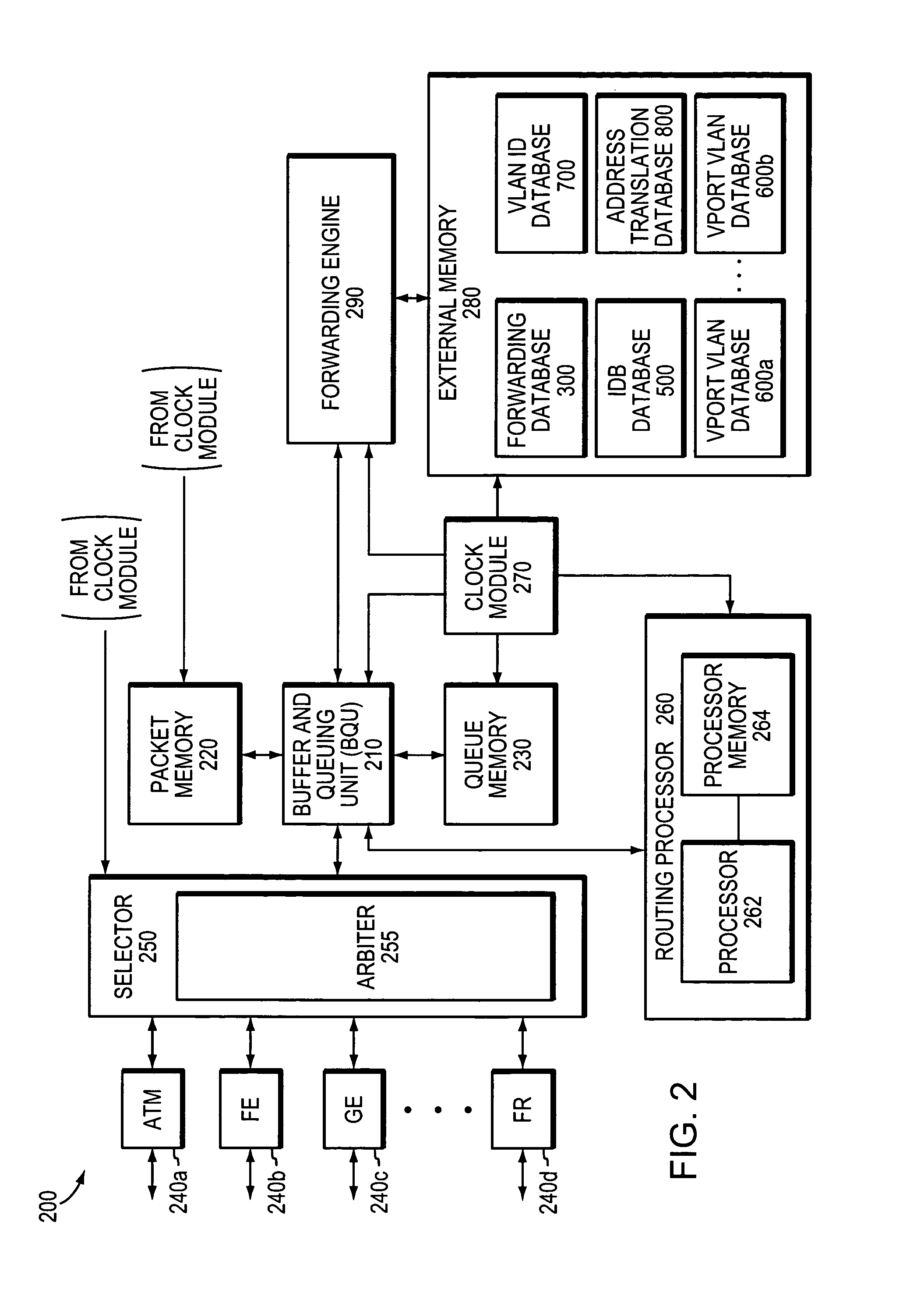
[0028]FIG. 1 is a schematic block diagram of an exemplary data network 100 that may be advantageously used with the present invention. The network 100 comprises a collection of communication links and segments connected to a plurality of nodes, such as end nodes 110 and intermediate nodes 200. The network links and segments may comprise local area networks (LANs) 120, LAN links 122, a wide-area network (WAN) 170, and WAN links 130 interconnected by intermediate nodes 200 to form an internetwork of computer nodes. These internetworked nodes communicate by exchanging data according to a predefined set of protocols, such as the Transmission Control Protocol / Internet Protocol (TCP / IP) and the Institute of Electrical and Electronics Engineers (IEEE) 802.3 and 802.1Q protocols.

[0029]Illustratively, data network 100 comprises a customer network portion belonging to a customer and a provider network portion belonging to a service provider (SP). The customer network portion comprises various...


PUM


Abstract

A technique transfers data between geographically dispersed entities belonging to a virtual-local-area network (VLAN). According to the technique, geographically dispersed entities communicate via software-defined virtual ports that “appear” as physical ports to the entities. Each virtual port, in turn, is associated with one or more connections wherein each connection may be associated with one or more VLANs. Data generated on a particular VLAN that is destined for a remote entity is forwarded to a virtual port which, in turn, transfers the data to the remote entity over the connection associated with the VLAN. Moreover, state is maintained at each virtual port for each connection, thereby enabling the virtual ports to support various protocols that operate with physical ports.

Description

BACKGROUND OF THE INVENTION[0001]1. Field of the Invention[0002]The present invention relates to data networking and, in particular, to a technique for coupling geographically dispersed entities belonging to a virtual local area network (VLAN) via virtual ports.[0003]2. Background Information[0004]A data network is a geographically distributed collection of interconnected communication links and segments for transporting data between nodes, such as computers. The nodes typically transport the data over the network by exchanging discrete frames or packets containing the data in accordance with various pre-defined protocols, such as the Transmission Control Protocol / Internet Protocol (TCP / IP) or the Internetwork Packet eXchange (IPX) protocol. In this context, a protocol consists of a set of rules defining how the nodes interact with each other.[0005]Many types of networks are available, with types ranging from local area networks (LANs) to wide area networks (WANs). LANs typically co...

Claims


Application Information

Patent Timeline
IPC IPC(8): H04L12/56
CPCH04L12/4645
Inventor INDIRESAN, ATRIMEO, GIOVANNIWU, MICHAEL T.KOBO, ROBERTO M.AHMED, SHAKEELLIAO, TAWEI
Owner CISCO TECH INC
Learn More