
Simultaneous filtering and compensation circuitry and method in chopping amplifier

a technology of compensation circuitry and amplifiers, applied in the direction of pulse technique, amplifiers with semiconductor devices/discharge tubes, electronic switching, etc., can solve the problems of unacceptably increasing the cost of chopper stabilized amplifiers, limiting the usability of otherwise highly desirable notch filtering chopper stabilized amplifier architecture, etc., to reduce the amount of integrated circuit chip area

Active Publication Date: 2009-09-08
TEXAS INSTR INC
View PDF4 Cites 14 Cited by
  • Summary
  • Abstract
  • Description
  • Claims
  • Application Information

AI Technical Summary

Benefits of technology

This approach significantly reduces the integrated circuit chip area needed for capacitors, allowing for more efficient use of chopper stabilized amplifiers in high-bandwidth applications by consolidating the roles of capacitors in both filtering and compensation.

Problems solved by technology

However, increases bandwidth of a notch filtered chopper stabilized amplifier requires higher transconductance Gm in the chopping circuitry and accordingly requires larger compensation capacitors and larger capacitors in the notch filter.
At higher bandwidths, the physical size of the compensation capacitors and notch filter capacitors causes them to occupy an unacceptably large amount of integrated circuit chip area, which unacceptably increases the cost of the chopper stabilized amplifier.
This limits the usability of the otherwise highly desirable notch filtered chopper stabilized amplifier architecture in complex mixed signal systems in which it would be highly desirable to include a number of such amplifiers on a single integrated circuit chip.

Method used


Image

  • Simultaneous filtering and compensation circuitry and method in chopping amplifier
  • Simultaneous filtering and compensation circuitry and method in chopping amplifier
  • Simultaneous filtering and compensation circuitry and method in chopping amplifier

Examples


Embodiment Construction

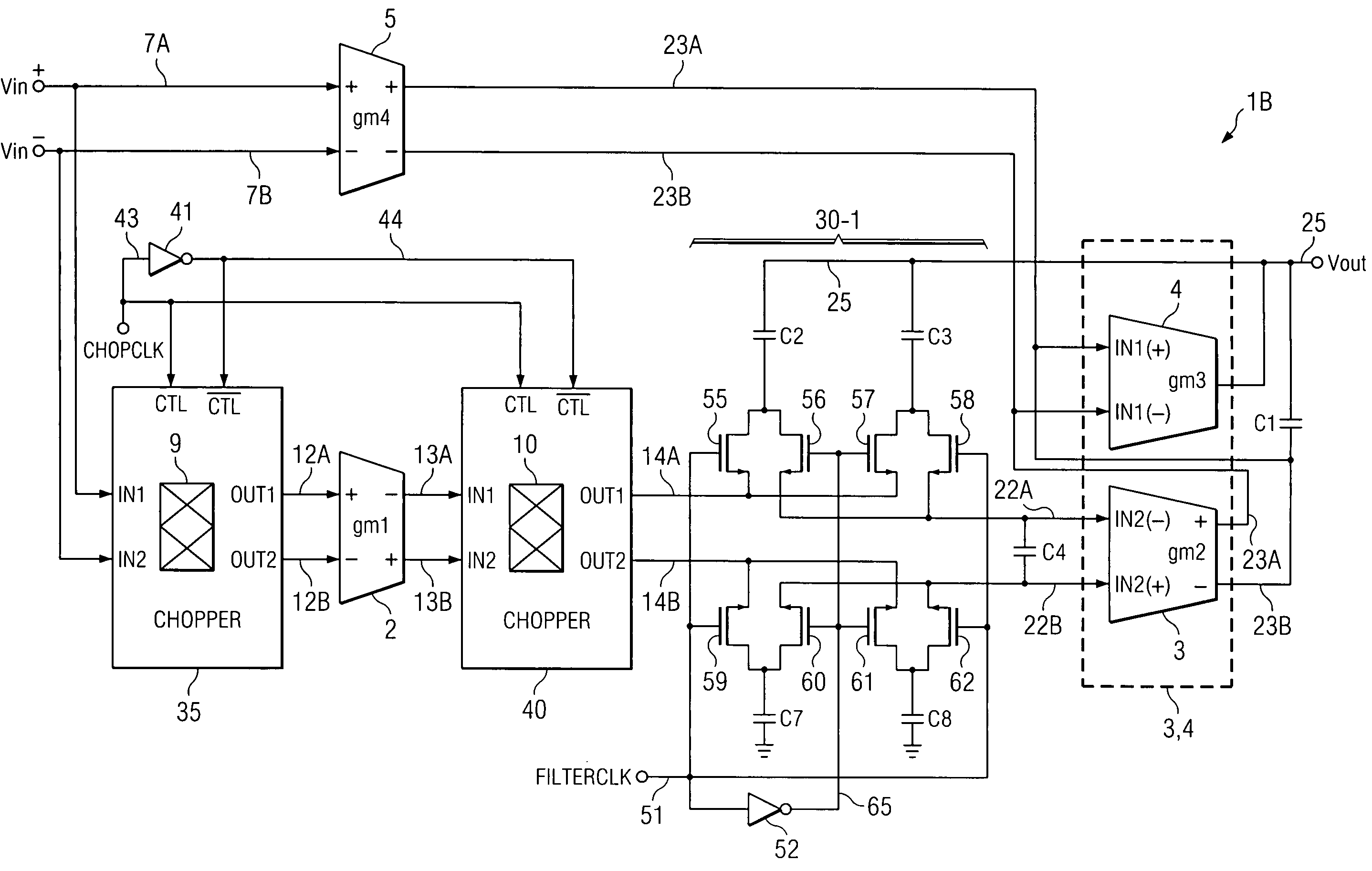
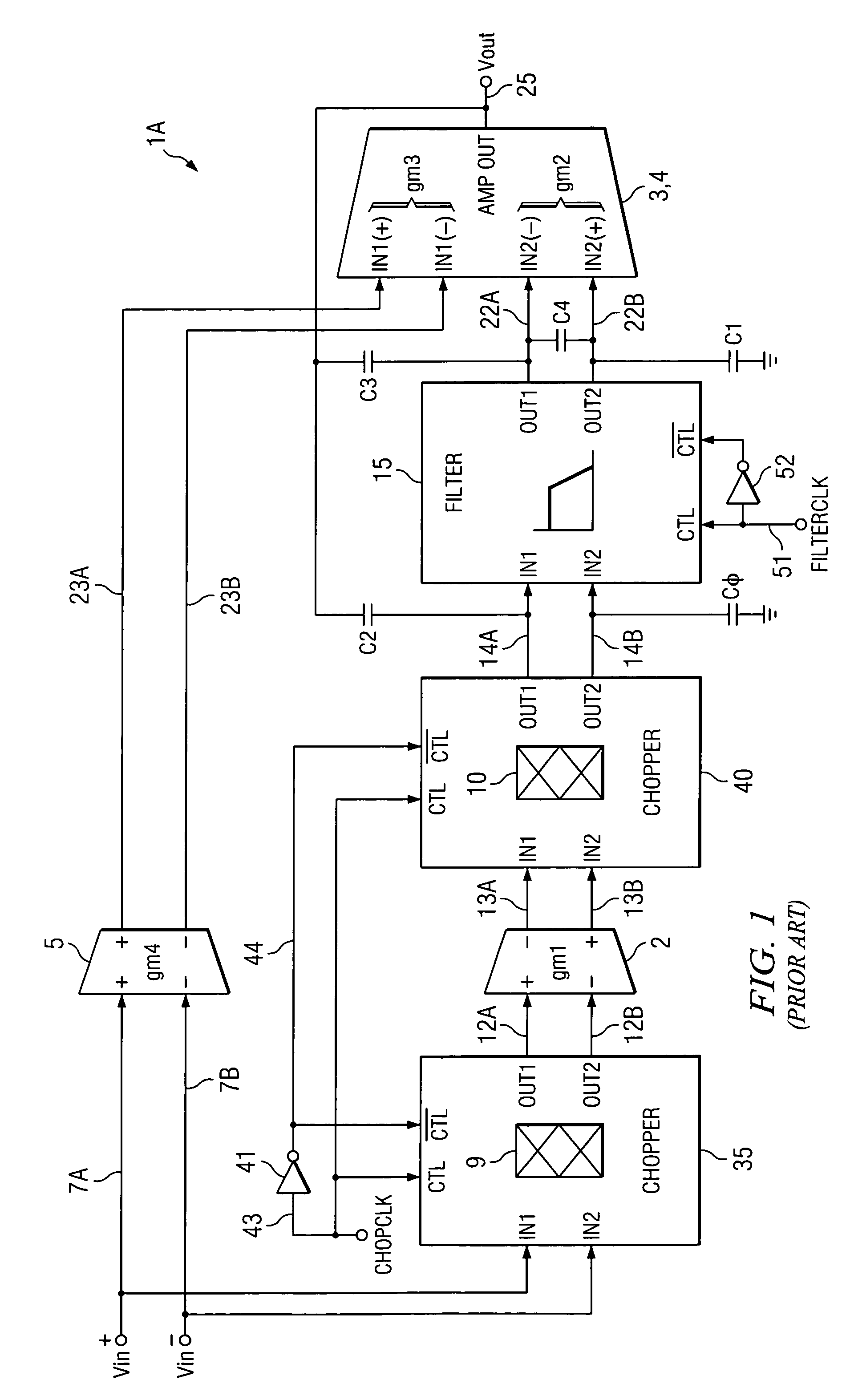
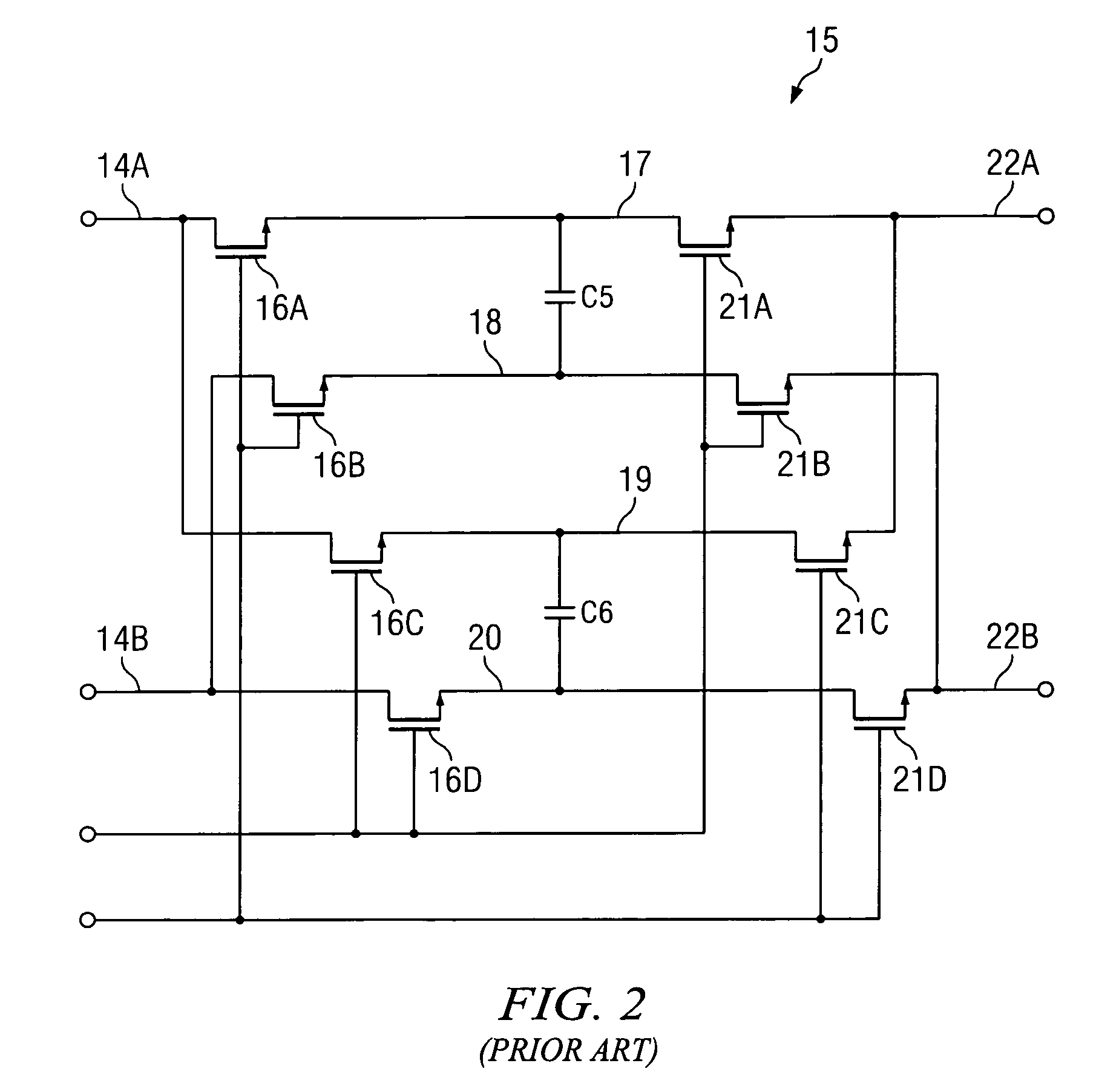
[0027]In accordance with the present invention, it was recognized that the capacitors within notch filter 15 of Prior Art FIG. 1 (i.e., capacitors C5 and C6 as shown in Prior Art FIG. 2) contribute very little to the overall compensation of chopper stabilized amplifier 1A, and similarly, Miller compensation capacitors C2 and C3 in Prior Art FIG. 1 contribute very little to the notch filtering. For a high-bandwidth implementation of chopper stabilized amplifier 1A in Prior Art FIG. 1, Miller compensation capacitors C2 and C3 and internal notch filter capacitors C5 and C6 occupy an undesirably large portion, e.g., as much as 40 to 60 percent, of the total integrated circuit chip area. Furthermore, if the chopper stabilized amplifier current is increased in order to increase the amplifier bandwidth, then even more capacitance is required for Miller compensation, and also for notch filtering (in order to keep voltages in notch filter 15 within predetermined limits).

[0028]In accordance w...


PUM


Abstract

A chopper-stabilized amplifier (1B) having a first output (25) includes an input chopper (9) for chopping an input signal and applying it to the input of a first amplifier (2) and an output chopper (10) for chopping an output signal of the first amplifier and applying it to the input of a switched capacitor notch filter (30-1). Notch filtering of the chopped output signal is performed by coupling a first compensation capacitor (C2) between a first output (25) of the chopper-stabilized amplifier and an output (14A) of the output chopper by means of a first switch (55) in response to a filter clock (FILTERCLK) and coupling a second compensation capacitor (C3) between the first output and an input (22A) of a second amplifier (3) by means of a second switch (58) in response to the filter clock, and coupling the first compensation capacitor between the first output and the input of the second amplifier by means of a third switch (56) in response to the complement of the filter clock and coupling the second compensation capacitor between the first output and the output (14A) of the output chopper circuit (40) by means of a fourth switch (57) in response to the complement.

Description

BACKGROUND OF THE INVENTION[0001]The present invention relates generally to chopper stabilized amplifiers, and more particularly to circuitry and techniques for reducing the amount chip area occupied by capacitors used for Miller compensation and notch filtering.[0002]Chopper stabilization is frequently used to improve offset and drift of amplifiers because it provides low in-band noise and avoids noise folding problems. A known technique for notch filtering can be used in chopper stabilized amplifiers to nearly eliminate the substantial output ripple voltage that otherwise occurs, and preserves the low offset, drift, and noise that are characteristic of the basic chopper stabilized amplifier topology. This known technique is described in the commonly assigned pending patent application Ser. No. 11 / 340,223 filed Jan. 26, 2006, entitled “Notch Filter for Ripple Reduction and Chopper Stabilized Amplifiers” by Rodney T. Burt and Joy Y. Zhang, incorporated herein by reference. However, ...

Claims


Application Information

Patent Timeline
Patent Type & Authority Patents(United States)
IPC IPC(8): H03F1/02
CPCH03F3/393
Inventor TRIFONOV, DIMITAR T.
Owner TEXAS INSTR INC
Learn More