
Protective sheet for laser processing and manufacturing method of laser processed parts

a technology of laser processing and manufacturing method, applied in the direction of film/foil adhesive, manufacturing tools, transportation and packaging, etc., can solve the problems of difficult to remove aftertreatment deposits, inability to meet demand, and inability to drill or drill with conventional drill or die, so as to achieve effective suppression of contamination of workpiece surface, high precision, and effective suppression of contamination

Inactive Publication Date: 2009-09-08
NITTO DENKO CORP
View PDF67 Cites 12 Cited by
  • Summary
  • Abstract
  • Description
  • Claims
  • Application Information

AI Technical Summary

Benefits of technology

The present invention relates to a protective sheet for laser processing that can effectively prevent contamination of workpiece surface by decomposition products when processing by ultraviolet absorption ablation of laser beam. The protective sheet is placed at the incident side of laser beam and acts as a barrier, preventing decomposition products from sticking to the workpiece surface. The protective sheet has low light transmissivity, preferably less than 50%, to prevent decomposition products from invading the interface area of the protective sheet and workpiece. The protective sheet is made of an aromatic polymer with high etching speed, and has an adhesive layer for increased contact tightness and suppression of contamination. The invention also provides a manufacturing method for laser processed parts using the protective sheet.

Problems solved by technology

In the conventional press processing or blanking process, the precision is about + / −100 μm at most, and such demand cannot be satisfied.
Drilling of materials is also demanded to conform to high definition and high precision, and drilling by using conventional drill or die cannot meet the needs.
The sticking strength of decomposition products is firm in proportion to power of laser beam, and when the power of laser beam is increased, it is difficult to remove deposits in aftertreatment.
As a result, improvement of throughput of processing is impeded, or reliability of cutting or drilling is lowered.

Method used


Image

  • Protective sheet for laser processing and manufacturing method of laser processed parts
  • Protective sheet for laser processing and manufacturing method of laser processed parts
  • Protective sheet for laser processing and manufacturing method of laser processed parts

Examples


reference example 1

[0178]The silicon wafer was processed by laser in the same manner as in Example 1, except that polyvinyl alcohol sheet (thickness: 50 μm, light transmissivity at wavelength 355 nm: 84.4%) was used as base material of protective sheet. As a result, the protective sheet was not cut off sufficiently, and the silicon wafer in the lower layer was processed by laser, and foams including decomposition product residue were generated between the protective sheet and silicon wafer. By peeling off the protective sheet, the opening area of the laser beam incident side of the silicon wafer was observed, and sticking of residue of scattering decomposition products of silicon wafer was recognized.

Example 2

[0179]On a base material (thickness: 13 μm, light transmissivity at wavelength 355 nm: 0%) made of polyimide (weight ratio of aromatic ring in repetition unit: 64 wt %), ultraviolet curable acrylic adhesive solution (2) was applied, and dried to form an adhesive layer (thickness 10 μm), and a pro...

example 5

[0185]A base material for protective sheet was manufactured by forming a sheet by casting a polymer obtained by copolymerization of 4-methyl-1-pentyne and 1,4-bis{2-[4-N,N-di(p-tolyl) amino) phenyl]vinyl} benzine at ratio by weight of 97 / 3.

[0186]The flexible printed board was processed by laser in the same manner as in Example 2, except that the above manufactured base material (ratio by weight of aromatic ring in repetition unit: 2.4 wt %, thickness: 10 μm, light transmissivity at wavelength 355 nm: 5%) was used as base material of protective sheet. As a result, cutting of protective sheet and flexible printed board was confirmed. After peeling off the protective sheet, the protective sheet gluing surface of the flexible printed board (the laser beam incident side) was observed particularly in the laser processing area, and decomposition products (deposits) were not observed.

(Second Aspect of the Invention)

[Measurement of Number-Average Molecular Weight]

[0187]Measured in the same m...

example 4

[0201]A polypropylene sheet of 20 μm in thickness was manufactured by mixing 99 parts by weight of polypropylene and 1 part by weight of carbon black, and fusing and extruding.

[0202]The silicon wafer was processed by laser in the same manner as in Example 2, except that the above manufactured polypropylene (etching rate: 0.45) was used as base material of protective sheet. After peeling off the protective sheet, the protective sheet gluing surface of the flexible printed board (the laser beam incident side) was observed particularly in the laser processing area, and decomposition products (deposits) were not observed.

[0203]As clear from the examples and comparisons, by using the protective sheet having a base material of which etching rate is 0.4 or more, contamination of surface of workpiece by decomposition products can be effectively suppressed.

(Third and Fourth Aspects of the Invention)

[Measurement of Number-Average Molecular Weight]

[0204]Measured in the same manner as in the fi...


PUM

PropertyMeasurementUnit
densityaaaaaaaaaa
extinction coefficientaaaaaaaaaa
ultraviolet region wavelength λaaaaaaaaaa

Abstract

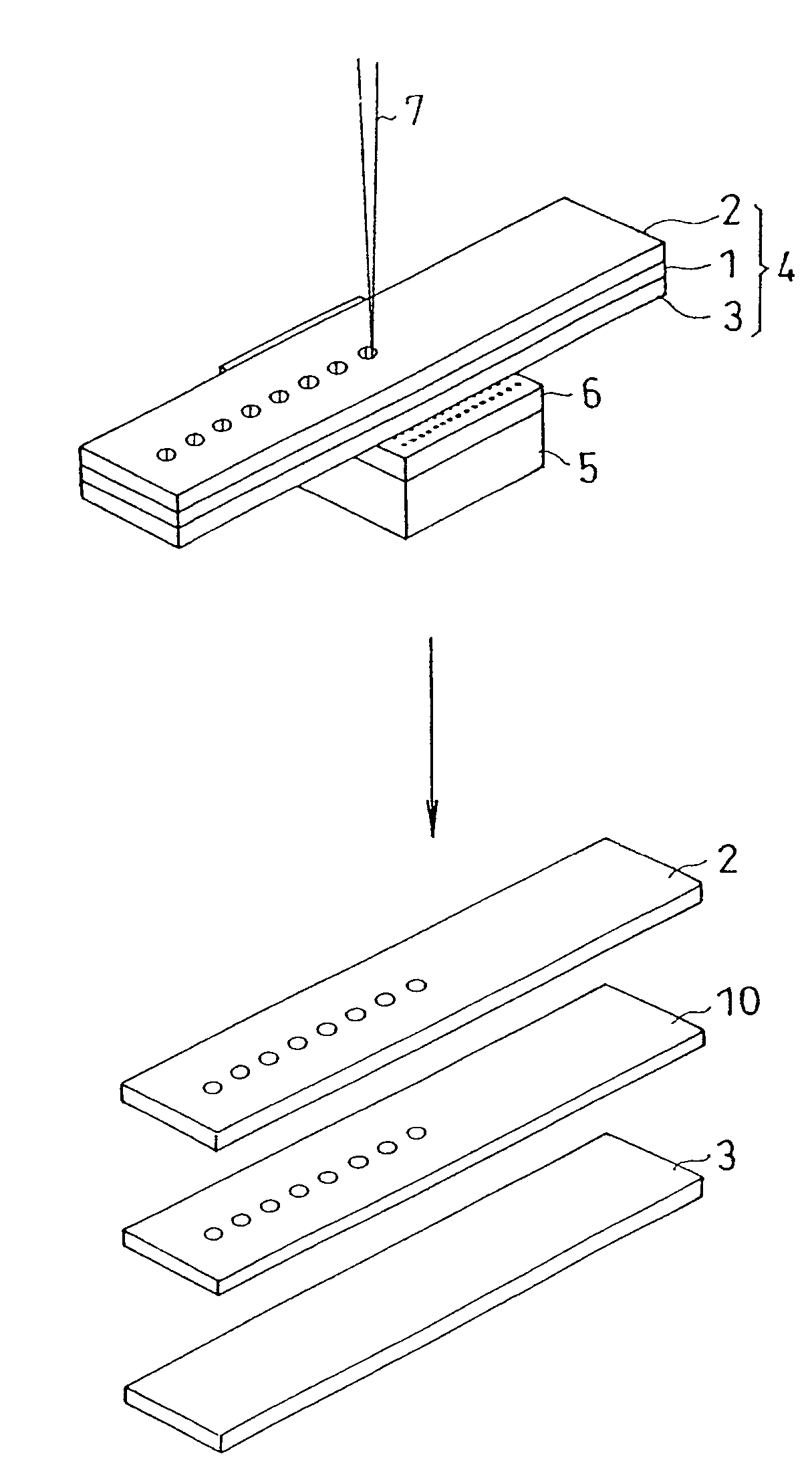
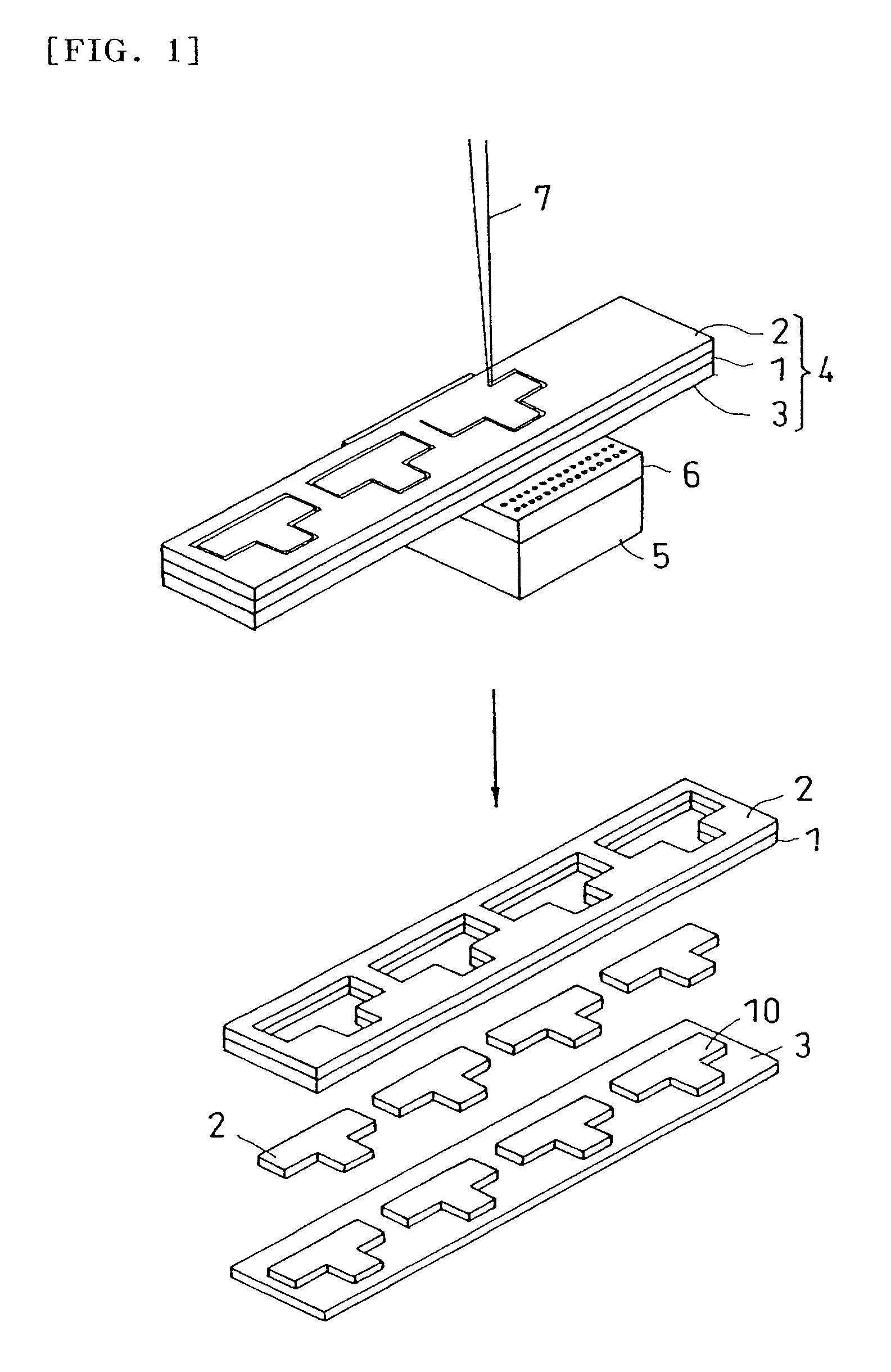
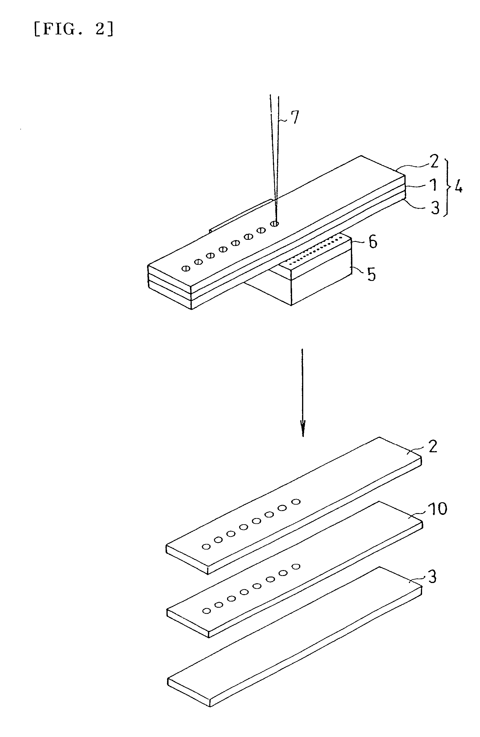
A laser processing protection sheet (2) capable of effectively preventing contamination on the surface of an article to be processed by decomposition products when the article to be processed (1) is processed by the UV absorption ablation of a laser beam (7). A production method for a laser processed article (10) using the laser processing protection sheet (2). The laser processing protection sheet (2) is provided on the laser beam incident surface side of the article to be processed (1) when the article (1) is processed by the UV absorption ablation of the laser beam (7).

Description

[0001]This application is the U.S. National Phase under 35 U.S.C. §371 of International Application PCT / JP2004 / 016268, filed Nov. 2, 2004, which claims priority to Japanese Patent Application No. 2003-430463, filed Dec. 25, 2003, Japanese Patent Application No. 2003-430451, filed Dec. 25, 2003, Japanese Patent Application No. 2004-100141, filed Mar. 30, 2004, Japanese Patent Application No. 2004-100199, filed Mar. 30, 2004, Japanese Patent Application No. 2004-100127, filed Mar. 30, 2004, Japanese Patent Application No. 2004-099896, filed Mar. 30, 2004, Japanese Patent Application No. 2004-100112, filed Mar. 30, 2004, and Japanese Patent Application No. 2004-100281, filed Mar. 30, 2004. The International Application was not published under PCT Article 21(2) in English.TECHNICAL FIELD[0002]The present invention relates to a protective sheet for laser processing used when processing a workpiece by ultraviolet absorption ablation by laser beam. The invention also relates to a manufactu...

Claims


Application Information

Patent Timeline
Patent Type & Authority Patents(United States)
IPC IPC(8): B23K26/38B23K26/18C09J7/22H01L21/301
CPCB23K26/18B23K26/4075C09J7/0264H05K3/0026B23K2201/40Y10T428/28C09J2483/006H05K2203/1383C09J2425/006B23K26/40C09J7/22B23K2101/40B23K2103/50C09J2301/30
Inventor URAIRI, MASAKATSUHINO, ATSUSHIMATSUO, NAOYUKITAKAHASHI, TOMOKAZUMATSUMURA, TAKESHIYAMAMOTO, SYOUJI
Owner NITTO DENKO CORP
Learn More