
Lighting system with illuminance control

a technology of illuminance control and control system, which is applied in the direction of photometry, instruments, sustainable buildings, etc., can solve the problems of erroneous light illuminance measurements, and achieve the effect of saving energy, and reducing the predetermined light illuminance of the luminair

Inactive Publication Date: 2015-06-18
HESA LIGHT
View PDF4 Cites 26 Cited by
  • Summary
  • Abstract
  • Description
  • Claims
  • Application Information

AI Technical Summary

Benefits of technology

This patent is about a system and method for controlling the brightness of outdoor lighting. The system uses a motorized service vehicle with a light sensor to measure the actual light levels of each individual lamp. This vehicle can quickly and easily measure the light levels of many lamps in a large area, without being affected by pollution or dirt. The light sensor is securely attached to the vehicle, making sure it is working correctly. The system also allows for the adjustment of the brightness levels of the lamps through a wireless communication link, pulsating the light levels between two levels. This helps to reduce background light pollution and noise. Overall, the patent aims to provide a more efficient and effective way to control outdoor lighting levels.

Problems solved by technology

Furthermore, since the light sensor is mounted on the motorized service vehicle, it is also uncomplicated for relevant personnel to ensure that the light sensor functions correctly e.g. is unaffected by dirt or pollution that could attenuate light input to the sensor and therefore lead to erroneous light illuminance measurements.

Method used


Image

  • Lighting system with illuminance control
  • Lighting system with illuminance control
  • Lighting system with illuminance control

Examples


Embodiment Construction

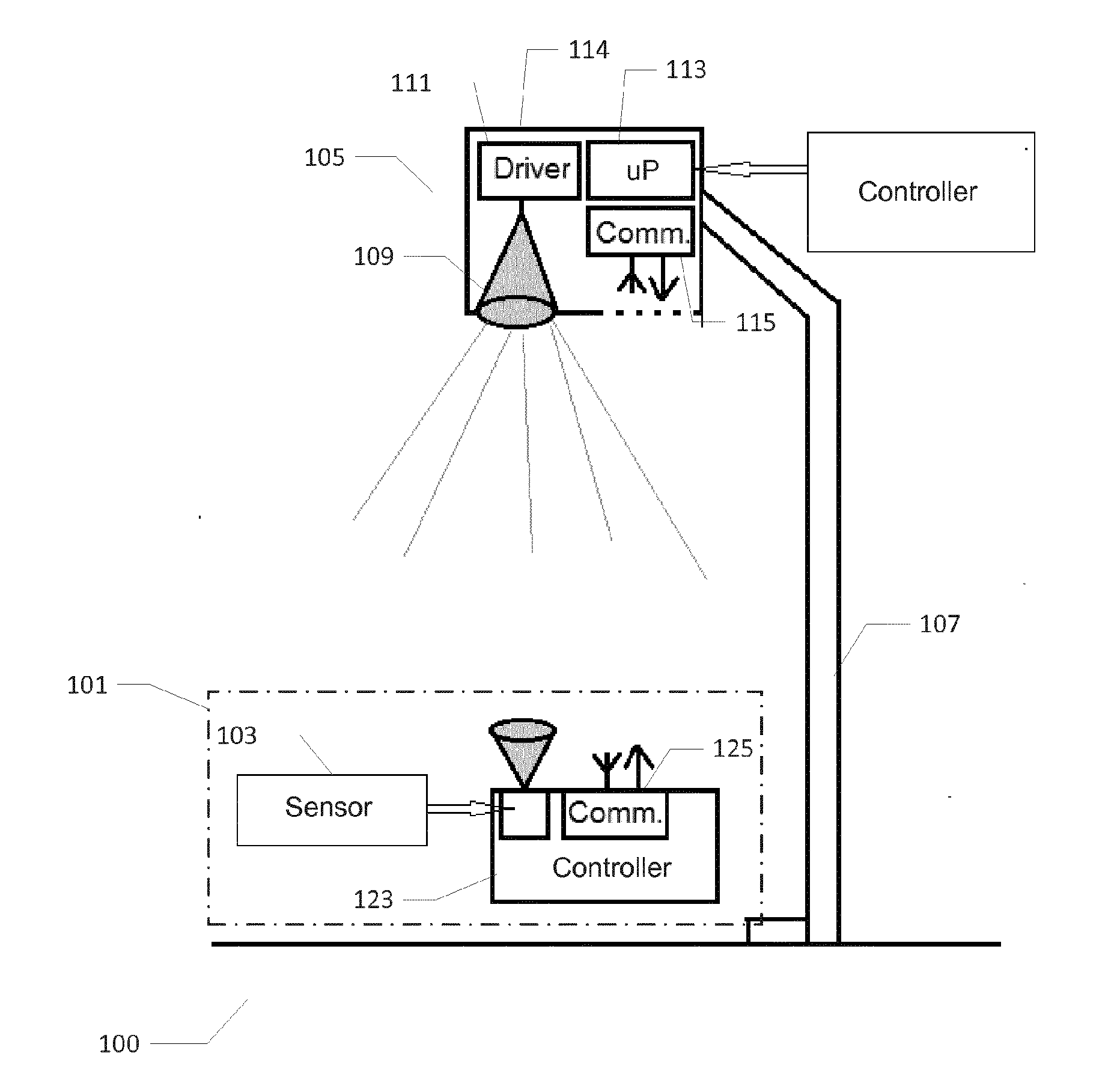
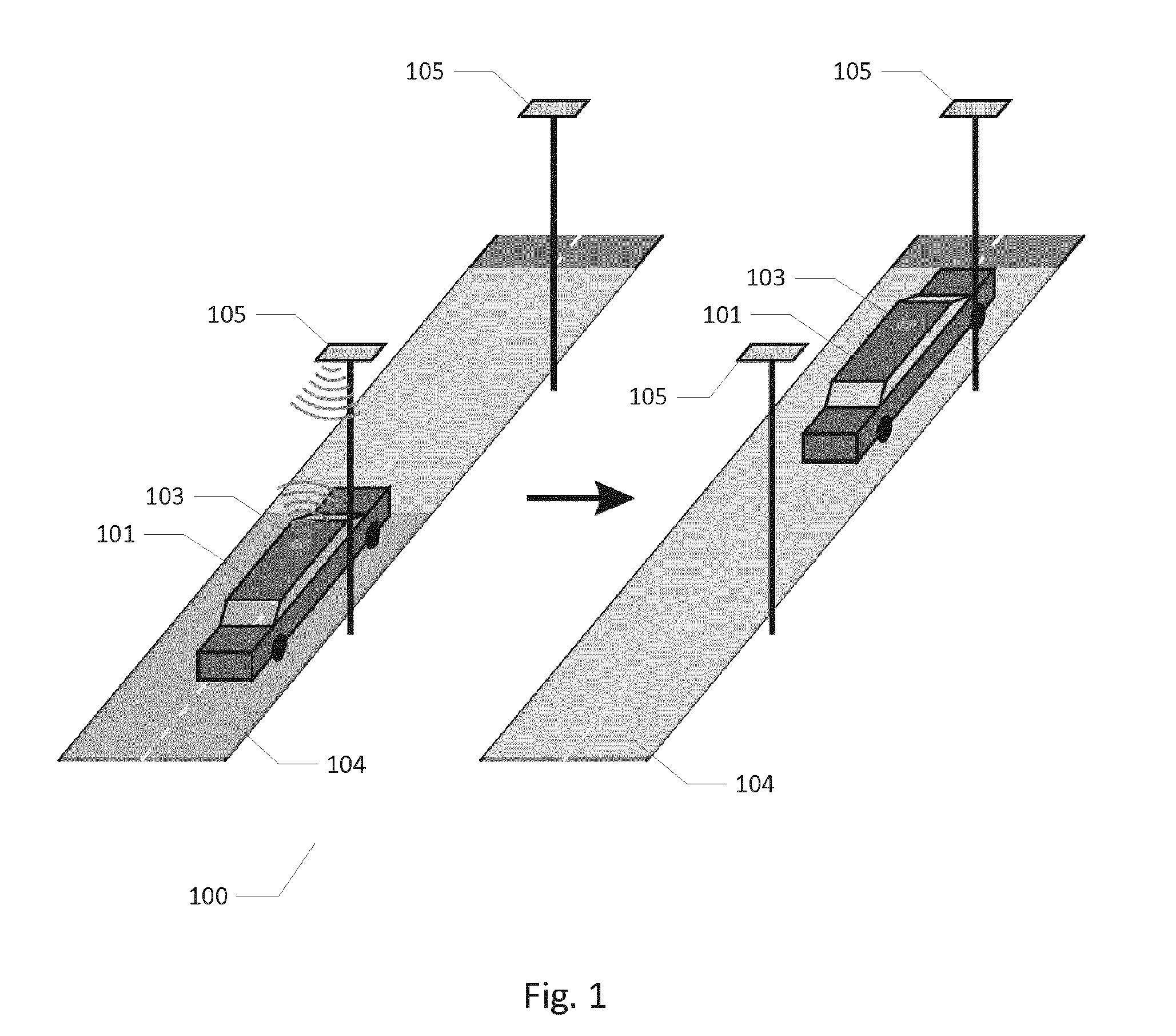
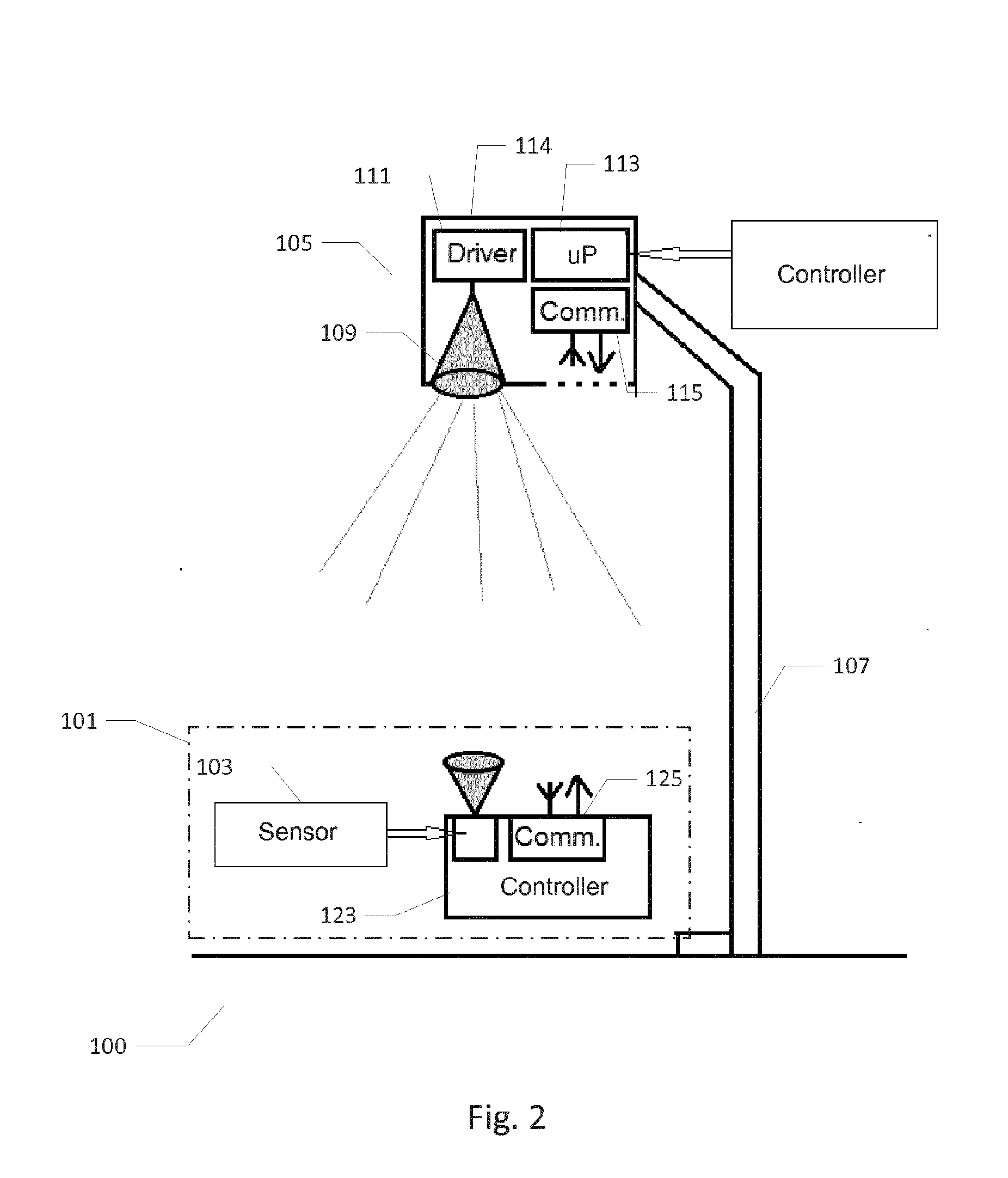
[0048]FIG. 1 illustrates schematically an illumination control system 100 comprising a plurality of outdoor luminaries 105 in accordance with a preferred embodiment of the invention. The illumination control system 100 preferably comprises a plurality of outdoor road luminaries 105 such as between 10 and 10.000. The illumination control system 100 furthermore comprises a motorized service vehicle 101 such as a car, a van, a motor cycle, a moped, an electrical bi-cycle etc. driven a service person The motorized service vehicle 101 comprises a light sensor or detector 103 which may be firmly attached to a suitable exterior chassis structure or body structure of the vehicle 101 keeping a fixed and known orientation of the light sensor or detector 103. Thereby, light generated by each of the plurality of outdoor luminaries 105 is able to travel to and illuminate the light sensor 103 in an unobstructed manner when the motorized service vehicle 101 passes the outdoor luminaire in question...


PUM


Abstract

The present invention relates to an illumination control system comprising a plurality of outdoor luminaries and a motorized service vehicle. Each luminaire comprises a controllable light source producing a light illuminance. The motorized service vehicle comprises a light sensor configured to detect the light illuminance generated by the controllable light source at the motorized service vehicle. The motorized service vehicle computes light illuminance data based on the detected light illuminance and transmits these to the outdoor luminaire through a wireless communication link or stores the light illuminance data on a data recording device of the motorized service vehicle. The outdoor luminaire receives may use the light illuminance data to set or adjust a light illuminance of the controllable light source.

Description

[0001]The present invention relates to an illumination control system comprising a plurality of outdoor luminaries and a motorized service vehicle. Each luminaire comprises a controllable light source producing a light illuminance. The motorized service vehicle comprises a light sensor configured to detect the light illuminance generated by the controllable light source at the motorized service vehicle. The motorized service vehicle computes light illuminance data based on the detected light illuminance and transmits these to the outdoor luminaire through a wireless communication link or stores the light illuminance data on a data recording device of the motorized service vehicle. The outdoor luminaire may use the light illuminance data to set or adjust a light illuminance of the controllable light source.BACKGROUND OF THE INVENTION[0002]It is important to secure that an appropriate light illuminance is provided by street and road lighting systems comprising a plurality of outdoor l...

Claims


Application Information

Patent Timeline
IPC IPC(8): H05B37/02H05B33/08H05B44/00
CPCH05B37/0227H05B37/0272H05B33/0872H05B33/0848H05B37/0245G01J2001/4247G01J1/0219G01J1/4228H05B47/11H05B47/19Y02B20/40H05B45/22H05B45/14H05B45/20H05B47/16H05B47/18H05B47/175Y02B20/72
Inventor PEDERSEN, HENRIK CHRESTENLARSEN, HENNING ENGELBRECHT
Owner HESA LIGHT
Learn More