
Electroblowing web formation process

a technology of fiber web and electroblowing, which is applied in the direction of filament/thread forming, monocomponent polyether artificial filament, fibre treatment, etc., can solve the problems of the coupling distance of the spinning nozzle to the voltage used, and the need for quite high voltage use, etc., to achieve the effect of sufficient strength

Active Publication Date: 2009-09-08
DUPONT SAFETY & CONSTR INC
View PDF13 Cites 17 Cited by
  • Summary
  • Abstract
  • Description
  • Claims
  • Application Information

AI Technical Summary

Benefits of technology

The present invention is about a process for making a fibrous web using an electroblowing process. This involves using an electric field to charge a polymer stream as it comes out of a spinning nozzle. The charged polymer stream is then collected on a collector to form a fibrous web. The technical effect of this invention is the ability to produce a high-quality fibrous web with improved properties, such as increased strength and flexibility.

Problems solved by technology

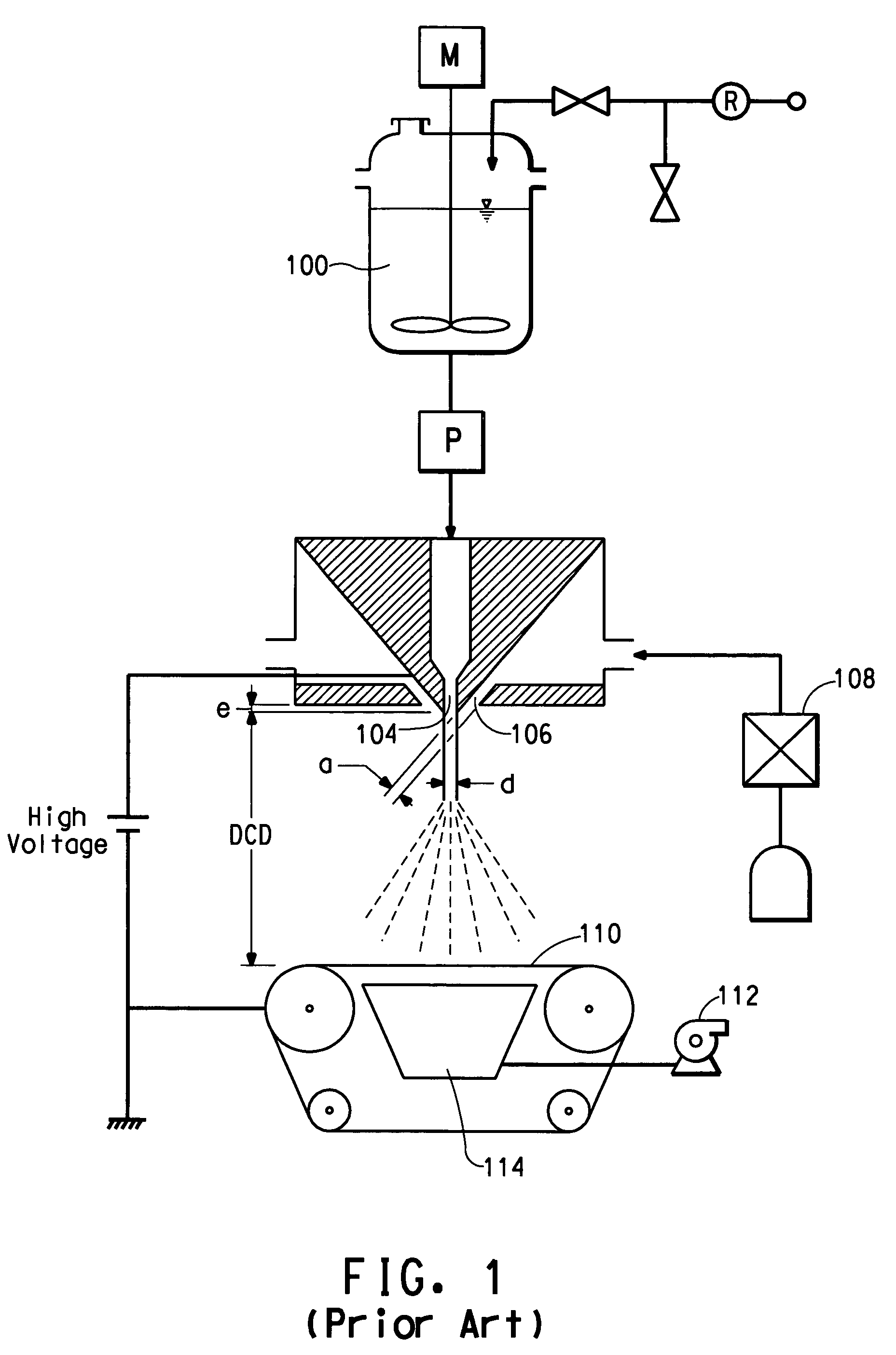
There are several disadvantages to the process disclosed in PCT publication no.
One disadvantage of the prior art is the necessity of using a quite high voltage.
Still another disadvantage of the prior art is the coupling of the spinning nozzle to collector distance to the voltage used.

Method used


Image

  • Electroblowing web formation process
  • Electroblowing web formation process
  • Electroblowing web formation process

Examples


example 1

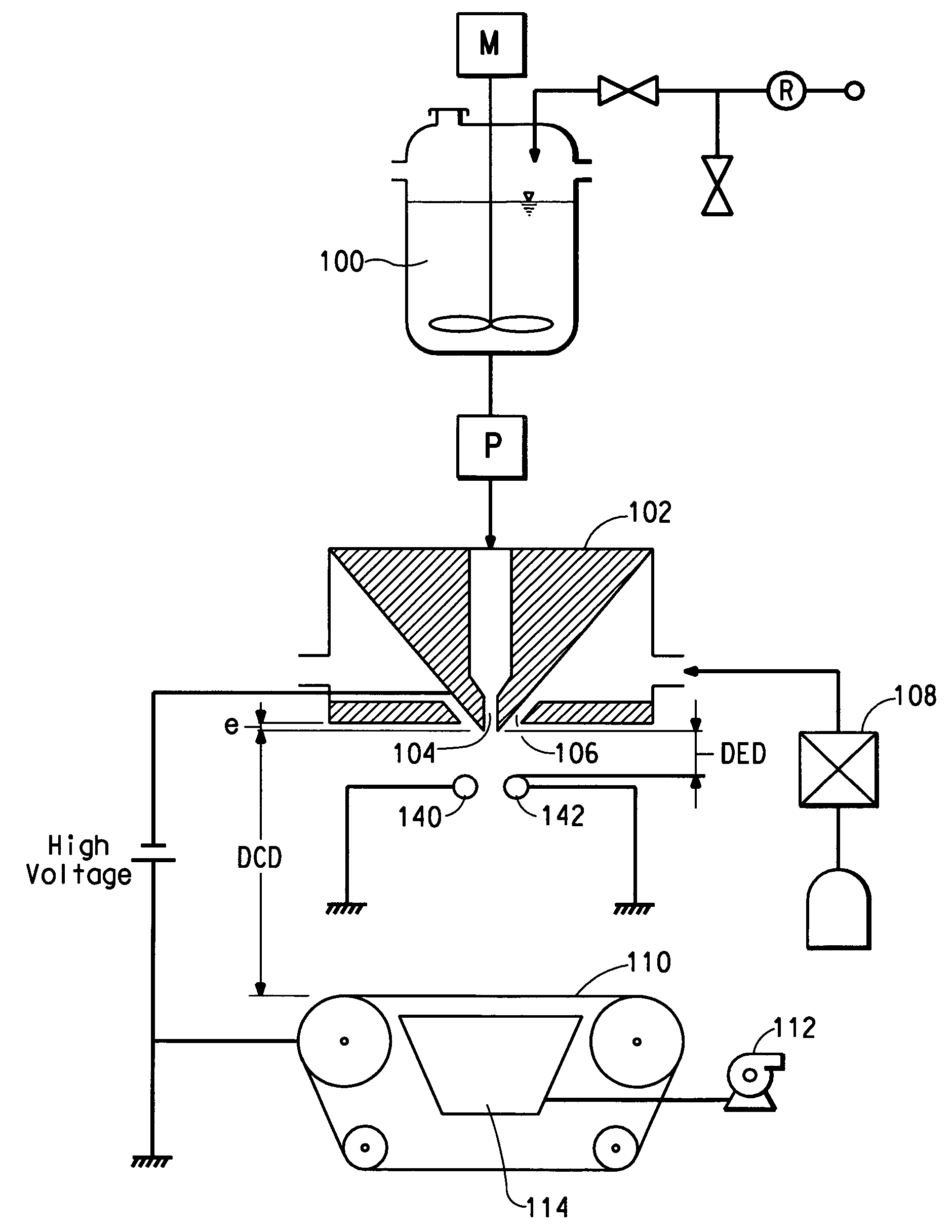
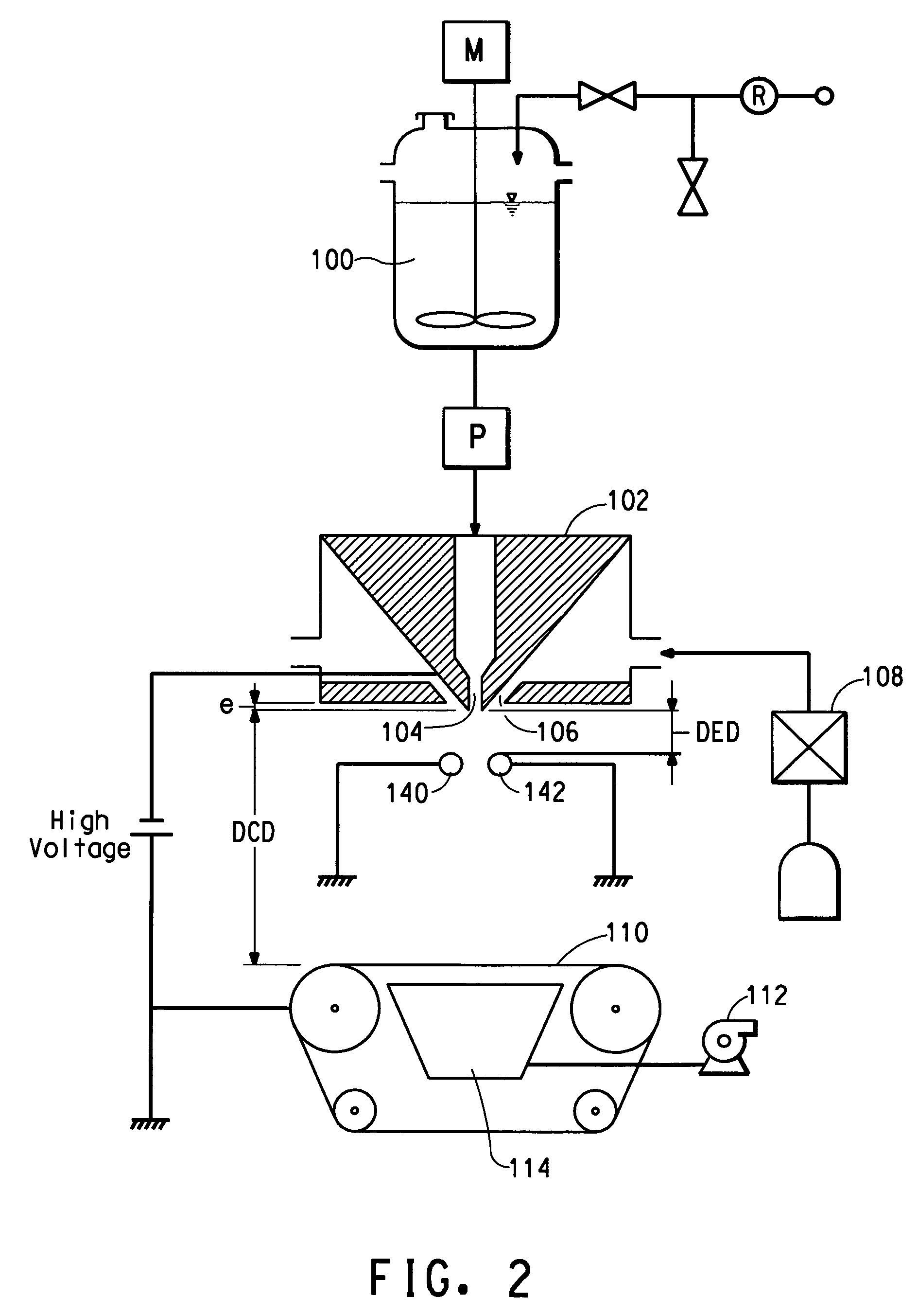
[0026]Poly(ethylene oxide) (PEO), viscosity average molecular weight (Mv) ˜300,000, available from Sigma-Aldrich, St Louis, Mo. is dissolved in deionized water to make a 10% by weight PEO solution. The solution electrical conductivity is measured to be 47 Micro-Siemens / cm using a VWR digital conductivity meter available from VWR Scientific Products (VWR International, Inc., West Chester, Pa.). The solution is spun in a single orifice electroblowing apparatus comprising a 26 gauge blunt syringe needle, in a concentric forwarding air jet. The needle tip protrudes 2.5 mm below the conductive face of the spin pack body. A high voltage is applied to the spin pack body and the spin orifice. The PEO solution is directed through a ring-shaped electrode, which is electrically grounded through an ammeter. Suitable process conditions are in the Table, below.

[0027]PEO fibers are formed via this process and are collected on a conductive surface and examined under a scanning electron microscope. ...

example 2

[0028]The procedure of Example 1 is followed except with a smaller inside diameter electrode, with the electrode located closer to the die tip and with a lower voltage applied to the spinneret. Suitable process conditions are listed in the Table, below. Nanofibers are collected having fiber diameters ranging from about 100 to about 700 nanometers.

[0029]The procedure of Example 2 shows that by decreasing the electrode inside diameter and decreasing the DED, the applied voltage to the spinneret can be reduced and still generate similar sized fibers as Example 1.

example 3

[0030]The procedure of Example 2 is repeated except with a slightly higher voltage on the spinneret. Suitable process conditions are listed in the Table, below. Nanofibers are collected having fiber diameters ranging from about 100 to about 700 nanometers.

[0031]

TABLESpinning ConditionsEx. 1Ex. 2Ex. 3Throughput (mL / min)0.50.50.5Volumetric Airflow (L / min)24.524.524.5Air Flow Velocity (m / s)121212Electrode Inside Diameter (mm)28.222.922.9Die to Electrode Distance (mm)25.412.712.7PolaritynegativenegativenegativeVoltage (kV)301416Die to Collector Distance (cm)303030


PUM

PropertyMeasurementUnit
voltageaaaaaaaaaa
voltageaaaaaaaaaa
distanceaaaaaaaaaa

Abstract

An improved electroblowing process is provided for forming a fibrous web of nanofibers wherein polymer stream is issued from a spinning nozzle in a spinneret with the aid of a forwarding gas stream, passes an electrode and a resulting nanofiber web is collected on a collector. The process includes applying a high voltage to the spinneret and grounding the electrode such that an electric field is generated between the spinneret and the electrode of sufficient strength to impart an electrical charge on the polymer as it issues from the spinning nozzle.

Description

FIELD OF THE INVENTION[0001]The present invention relates to a process for forming a fibrous web wherein a polymer stream is spun through a spinning nozzle into an electric field of sufficient strength to impart electrical charge on the polymer and wherein a forwarding gas stream aids in transporting the polymer away from the spinning nozzle.BACKGROUND OF THE INVENTION[0002]PCT publication no. WO 03 / 080905A discloses an apparatus and method for producing a nanofiber web. The method comprises feeding a polymer solution to a spinning nozzle to which a high voltage is applied while compressed gas is used to envelop the polymer solution in a forwarding gas stream as it exits the nozzle, and collecting the resulting nanofiber web on a grounded suction collector.[0003]There are several disadvantages to the process disclosed in PCT publication no. WO 03 / 080905A, particularly if the process is carried out on a commercial scale.[0004]One disadvantage of the prior art is the necessity of usin...

Claims


Application Information

Patent Timeline
Patent Type & Authority Patents(United States)
IPC IPC(8): H05B7/00
CPCD01D5/0092D01F6/66D04H3/16D04H3/03D04H1/56D01D5/0069B82Y40/00D01D5/00D04H1/728
Inventor BRYNER, MICHAEL ALLENARMANTROUT, JACK EUGENEARMSTRONG, JOHN EDWARDJOHNSON, BENJAMIN SCOTT
Owner DUPONT SAFETY & CONSTR INC
Learn More