
High performance filter media with internal nanofiber structure and manufacturing methodology

a technology of nanofibers and filter media, applied in the field of filter media, can solve the problems of needing a supporting substrate, risk of nanofiber layer delamination from the substrate, and more rapid plugging of the filter, and achieve the effect of high performan

Inactive Publication Date: 2005-02-03
FLEETGUARD INC
View PDF40 Cites 153 Cited by
  • Summary
  • Abstract
  • Description
  • Claims
  • Application Information

AI Technical Summary

Benefits of technology

[0001] The invention relates to filter media, and more particularly to filter media incorporating nanofibers of diameter less than 1 μm for high performance.
[0002] Filter media with nanofibers is known in the prior art. A nanofiber filter media layer is typically provided along an upstream face surface of a bulk filter media including a layer of coarse fibers. The nanofibers extend parallel to the face of the bulk filter media layer and provide high efficiency filtering of small particles in addition to the filtering of larger particles provided by the coarse filter media. The nanofibers are provided in a thin layer laid down on a supporting substrate and / or used in conjunction with protective layers in order to attain a variety of benefits, including increased efficiency, reduced initial pressure drop, cleanability, reduced filter media thickness and / or to provide an impermeability barrier to certain fluids, such as water droplets. Prior approaches have several inherent disadvantages, including the need for a supporting substrate, a risk of delamination of the nanofiber layer from the substrate, more rapid plugging of the filter by captured contaminants, and the alignment of nanofibers parallel to the media face surface.

Problems solved by technology

Prior approaches have several inherent disadvantages, including the need for a supporting substrate, a risk of delamination of the nanofiber layer from the substrate, more rapid plugging of the filter by captured contaminants, and the alignment of nanofibers parallel to the media face surface.

Method used


Image

  • High performance filter media with internal nanofiber structure and manufacturing methodology
  • High performance filter media with internal nanofiber structure and manufacturing methodology
  • High performance filter media with internal nanofiber structure and manufacturing methodology

Examples


Embodiment Construction

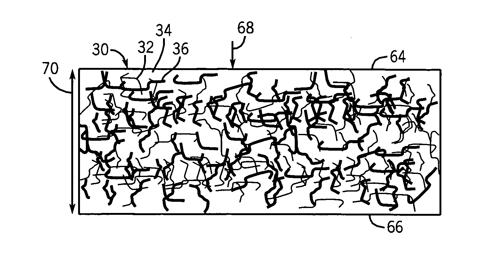
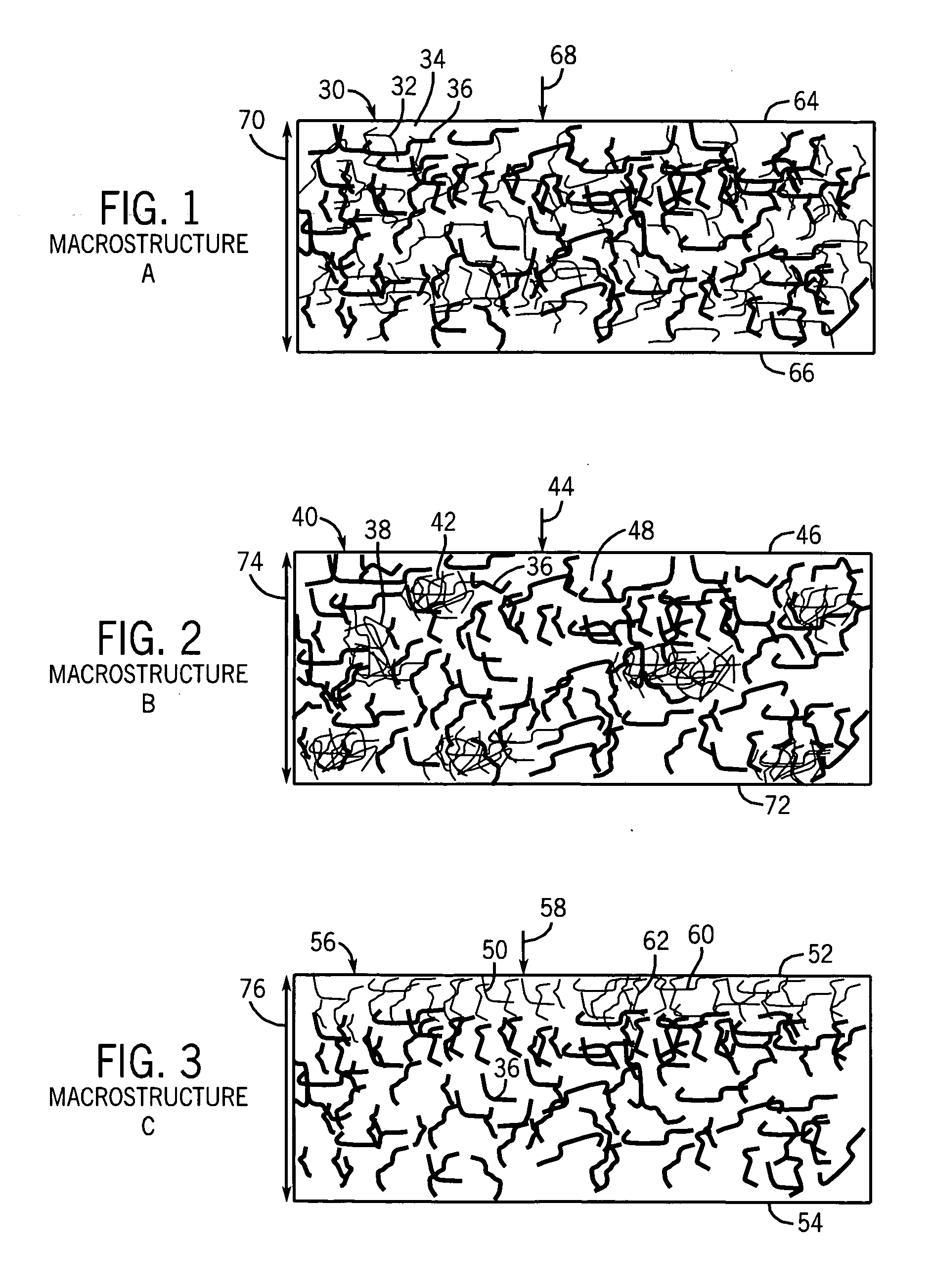
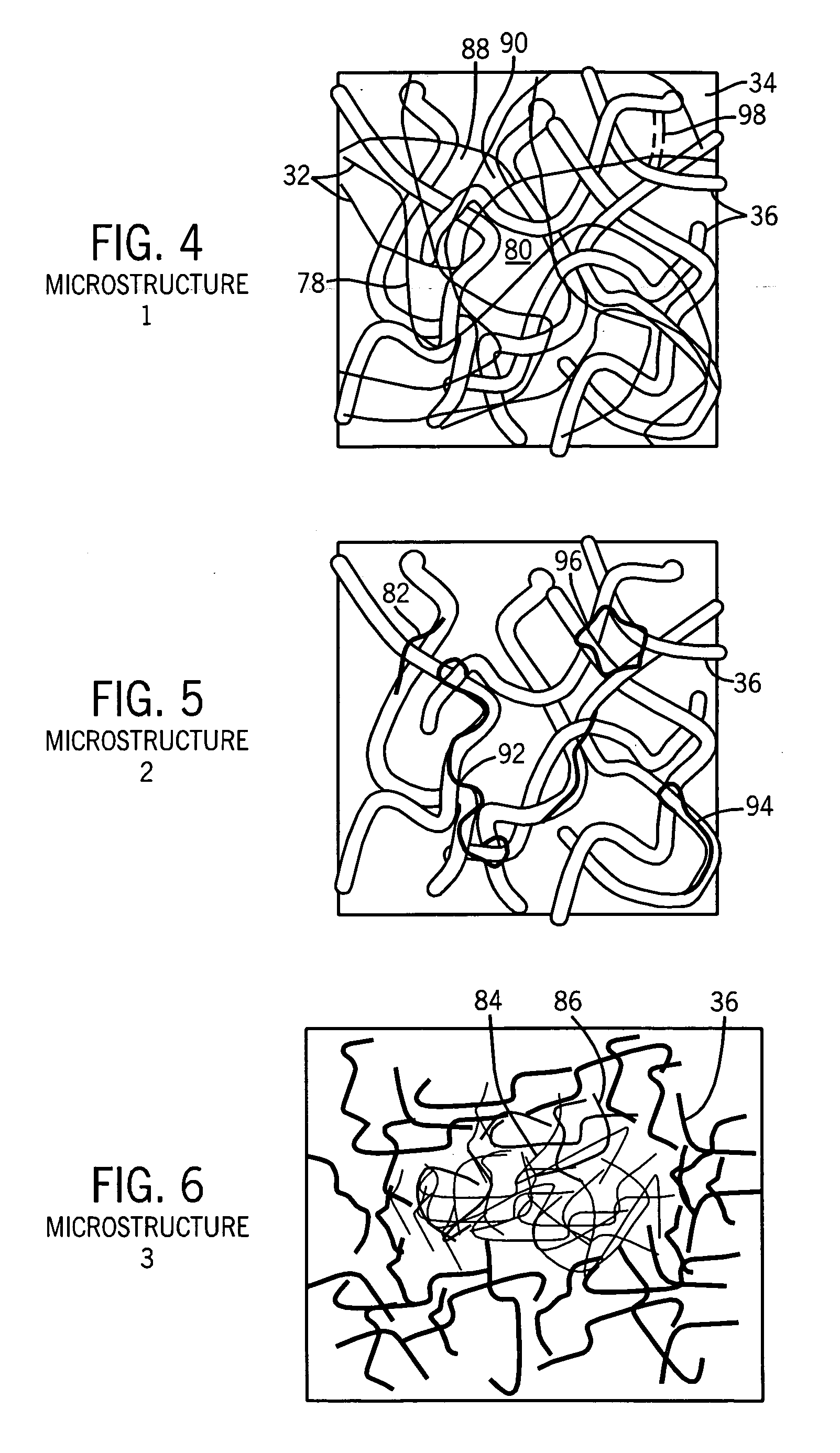
[0025]FIG. 1 shows high performance filter media 30 having nanofibers 32 of diameter less than 1 μm incorporated and processed into internal structure of a filter medium 34 dominantly composed of coarse fibers 36 of diameter greater than 1 μm. In some embodiments, to be described, nanofibers 32 and coarse fibers 36 are of different materials. Nanofibers 32 are preferably selected from the group consisting of: polymeric materials; ceramic materials; acrylic; nylon; polyvinyl alcohol; polymeric halocarbon; polyester; polyaramid; polyphenylsulfide; cellulose; titania; glass; alumina; and silica. Coarse fibers 36 are preferably selected from the group consisting of: polymeric materials; ceramic materials; polyvinyl alcohol; cellulose; acrylic; polyester; polyaramid; titania; glass; silica; nylon; polyphenylsulfide; polymeric halocarbon; and alumina. The ratio of coarse fiber diameter to nanofiber diameter is between 10 and 1,000. In some embodiments, particularly for liquids, the nanofi...


PUM

PropertyMeasurementUnit
Fractionaaaaaaaaaa
Fractionaaaaaaaaaa
Fractionaaaaaaaaaa

Abstract

High performance filter media and manufacturing methodology provides nanofibers of diameter less than 1 μm incorporated and processed into internal structure of a filter medium dominantly composed of coarse fibers of diameter greater than 1 μm, to change the internal media structure.

Description

BACKGROUND AND SUMMARY OF THE INVENTION [0001] The invention relates to filter media, and more particularly to filter media incorporating nanofibers of diameter less than 1 μm for high performance. [0002] Filter media with nanofibers is known in the prior art. A nanofiber filter media layer is typically provided along an upstream face surface of a bulk filter media including a layer of coarse fibers. The nanofibers extend parallel to the face of the bulk filter media layer and provide high efficiency filtering of small particles in addition to the filtering of larger particles provided by the coarse filter media. The nanofibers are provided in a thin layer laid down on a supporting substrate and / or used in conjunction with protective layers in order to attain a variety of benefits, including increased efficiency, reduced initial pressure drop, cleanability, reduced filter media thickness and / or to provide an impermeability barrier to certain fluids, such as water droplets. Prior app...

Claims


Application Information

Patent Timeline
IPC IPC(8): B01D39/00B01D39/08B01D39/14B01D39/16B01D39/20B82B1/00B82B3/00
CPCB01D39/20B01D39/16Y10S264/48Y10S428/903Y10T442/608Y10T442/626Y10T442/614Y10T442/615
Inventor VERDEGAN, BARRY M.FALLON, STEPHEN L.PARDUE, BYRON A.HABERKAMP, WILLIAM C.
Owner FLEETGUARD INC
Learn More