Automotive engine-cooling fan assembly

a technology for engine cooling fans and fan assemblies, which is applied to non-positive displacement fluid engines, positive displacement liquid engines, liquid fuel engine components, etc., can solve the problems of engine cooling fan assemblies that suffer from harshness, etc., and achieves the effect of reducing noise and vibration, higher than desirable levels of noise, vibration, and harshness

Active Publication Date: 2009-09-08
ROBERT BOSCH CORP
View PDF13 Cites 18 Cited by
  • Summary
  • Abstract
  • Description
  • Claims
  • Application Information

AI Technical Summary

Benefits of technology

[0008]It is desirable when designing an automotive engine-cooling fan assembly to minimize noise and vibration. Some engine-cooling fan assemblies may suffer from higher than desirable levels of noise, vibration, and harshness (“NVH”) caused by, for example, motor cogging torque, axial cogging forces, torque ripple, and axial ripple forces which can excite resonant modes in the fan structure.
[0009]The automotive engine-cooling fan assembly of the present invention decreases the excitation of torsional and axial modes of vibration of the fan while maintaining the air-moving performance, structural integrity, motor-cooling airflow, and low cost of the fan.

Problems solved by technology

Some engine-cooling fan assemblies may suffer from higher than desirable levels of noise, vibration, and harshness (“NVH”) caused by, for example, motor cogging torque, axial cogging forces, torque ripple, and axial ripple forces which can excite resonant modes in the fan structure.

Method used


Image

  • Automotive engine-cooling fan assembly
  • Automotive engine-cooling fan assembly
  • Automotive engine-cooling fan assembly

Examples


Embodiment Construction

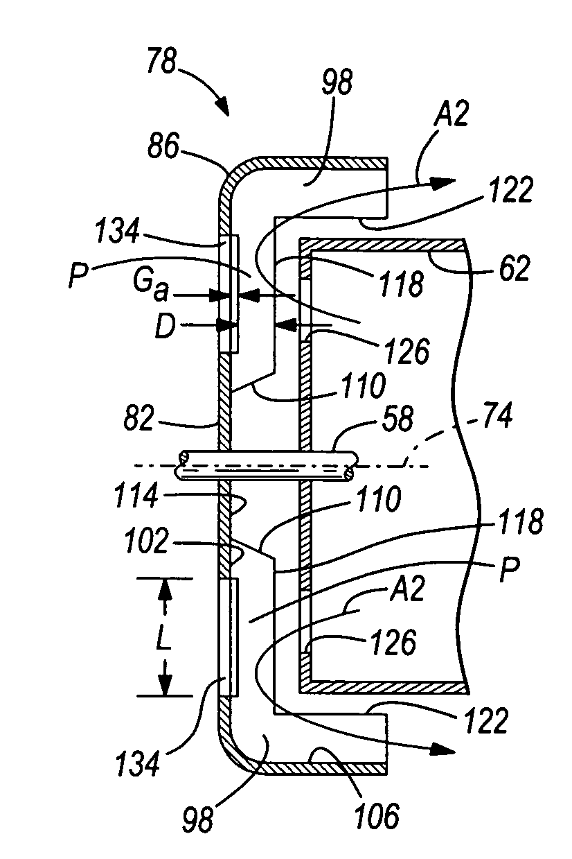
[0026]FIG. 4 illustrates an automotive engine-cooling fan assembly 50 of the present invention. The fan assembly 50 includes a fan 54 mounted to a driveshaft 58 of a motor 62, which may be supported by a fan shroud 66 or another structure. The fan shroud 66 is positioned adjacent a heat exchanger 70 (e.g., a radiator), such that rotation of the fan 54 about a central axis 74 (see FIG. 5) of the driveshaft 58 generates an airflow A1 through the heat exchanger 70.

[0027]The fan 54 includes a hub 78 having an inner hub portion 82 and an outer hub portion 86. The inner hub portion 82 defines a substantially planar face that extends radially with respect to the central axis 74 and is coupled to the driveshaft 58 for rotation with the driveshaft 58. The inner hub portion 82 may be coupled to the driveshaft 58 using any of a number of components and methods known in the art. Although the illustrated inner hub portion 82 is shown directly coupled to the driveshaft 58, it should be understood...


PUM


Abstract

The present invention provides an automotive engine-cooling fan assembly including a motor having a driveshaft defining a central axis, and a fan driven by the motor. The fan includes an inner hub portion coupled to the driveshaft, and an outer hub portion coupled to the inner hub portion. The outer hub portion is coupled to a plurality of radially-extending blades. The fan also includes a plurality of vibration isolation members interconnecting the inner hub portion and the outer hub portion.

Description

RELATED APPLICATIONS[0001]This application claims priority to U.S. Provisional Patent Application Ser. No. 60 / 466,139 filed on Apr. 28, 2003, which is incorporated herein by reference.FIELD OF THE INVENTION[0002]The present invention relates generally to fan assemblies, and more particularly to automotive engine-cooling fan assemblies.BACKGROUND OF THE INVENTION[0003]Typical automotive engine-cooling fan assemblies include an electric motor having a driveshaft coupled to a fan. The typical fan includes a hub which extends from the driveshaft to the roots of fan blades extending from the hub. The hub typically has a face portion which extends radially outwardly from the driveshaft attachment to a cylindrical portion to which the fan blades are attached. To conserve axial space, the motor is typically positioned on the concave side of the hub such that at least a portion of the motor is within the cylindrical portion of the hub. An opposite or a convex side of the hub guides air towar...

Claims


Application Information

Patent Timeline
Patent Type & Authority Patents(United States)
IPC IPC(8): F04B39/06A47C7/74B63H1/16F04D25/08F04D29/32F04D29/66
CPCF01D5/34F04D25/082H02K9/06F04D29/668F04D29/329F04D29/5806
Inventor CAPLAN, MARK D.KEHRER, WOLFGANGYAPP, MARTIN G.
Owner ROBERT BOSCH CORP
Why Eureka
Try Eureka