
Architecture for electric machine

a technology for electric machines and circuits, applied in the direction of machines/engines, electric generator control, dynamo-electric converter control, etc., can solve the problems of internal fault currents that can become extremely destructive to the machine, limited their usefulness, etc., and achieve the effect of reducing the stray inductance of the end turn

Inactive Publication Date: 2009-09-01
PRATT & WHITNEY CANADA CORP
View PDF194 Cites 912 Cited by
  • Summary
  • Abstract
  • Description
  • Claims
  • Application Information

AI Technical Summary

Benefits of technology

The present invention provides a method for operating a gas turbine engine using an electric machine to generate power. The engine is connected to an electrical distribution system in parallel relative to one another. In the event of a fault, the engine can shut down at least one channel associated with the fault while continuing operation of a remainder of the channels to provide power output to the electrical distribution system. Additionally, the invention provides an alternator with a stator having at least one stator winding with multiple end turns exposed at an axial end of the stator, a fluid cooling jacket surrounding the stator and the end turns, and an insert disposed intermediate the end turns and the cooling jacket, the insert having jets for directing fluid coolant from the cooling jacket to the end turns, the insert made of at least one of copper and aluminium to reduce stray inductance of the end turns.

Problems solved by technology

Prior art PM machines (and particularly PM alternators) suffer from at least two limitations which has limited their usefulness somewhat, namely: (1) the output of the PM alternator may only be controlled within the machine (i.e. varied) by varying the rotor speed (assuming a fixed geometry machine), and (2) if a short circuit or other internal fault occurs in the machine, the internal fault current can become extremely destructive to the machine, particularly in high power applications.
With reference to the first drawback, this intrinsic feature particularly limits the usefulness of a PM generator in circumstances where the rotor rotation speed cannot be independently controlled.
The problem is an order of magnitude greater for certain military applications, where cruise speed is rarely maintained for any length of time.
The prior art therefore poses optimization problems to the ISG designer, where critical over-power and under-power scenarios must be managed to achieve a satisfactory design.
There are other drawbacks inherent prior art designs, which result in complicated mechanisms and fabrication techniques.
The device offers only limited control over operation of the machine, and its complexity makes it unsuitable for higher reliability and lighter weight applications such as, for example, aircraft applications.

Method used


Image

  • Architecture for electric machine
  • Architecture for electric machine
  • Architecture for electric machine

Examples


Embodiment Construction

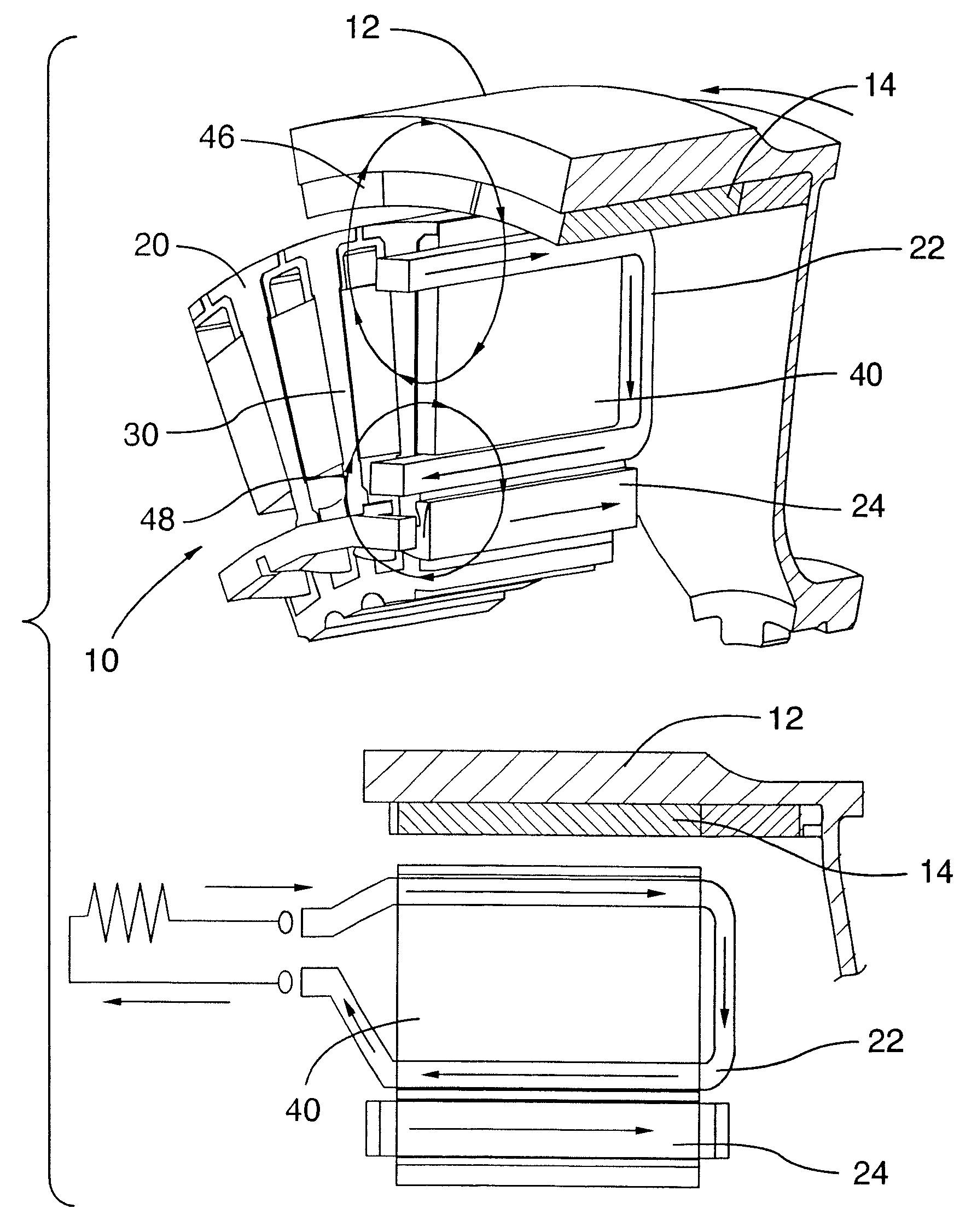
[0046]A permanent magnet (PM) machine according to the present invention is depicted in at 10 in FIGS. 4A to 4E. Referring first to FIGS. 4A and 4B, PM machine 10 has a rotor 12 which includes a plurality of permanent magnets 14 retained by a yoke 16 and retention sleeve portion 18. Machine 10 also has a stator 20 which includes at least a primary winding 22 and at least a secondary winding 24 (for clarity, only one of each such winding is shown), separated in this embodiment by a winding air gap 26 and disposed in radial slots 28 between a plurality of adjacent teeth 30 in a back iron 32. (For ease of illustration in FIG. 4B, the adjacent elements of secondary winding 24 are shown unconnected.) The winding air gap serves as insulation and may be replaced by other suitable insulation. A rotor air gap 34 separates rotor 12 and stator 20 in a typical fashion, and a stator tooth gap 36 separates adjacent teeth 30 at a rotor interface surface 38 of stator 20. Primary winding 22 and seco...


PUM


Abstract

The invention includes an electric machine having a rotor, stator and at least one winding in the stator adapted to conduct a current, and a secondary winding, electrically isolated from the first winding and inductively coupled to the first winding, which may be used to control at least one of the output voltage and current of the first winding.

Description

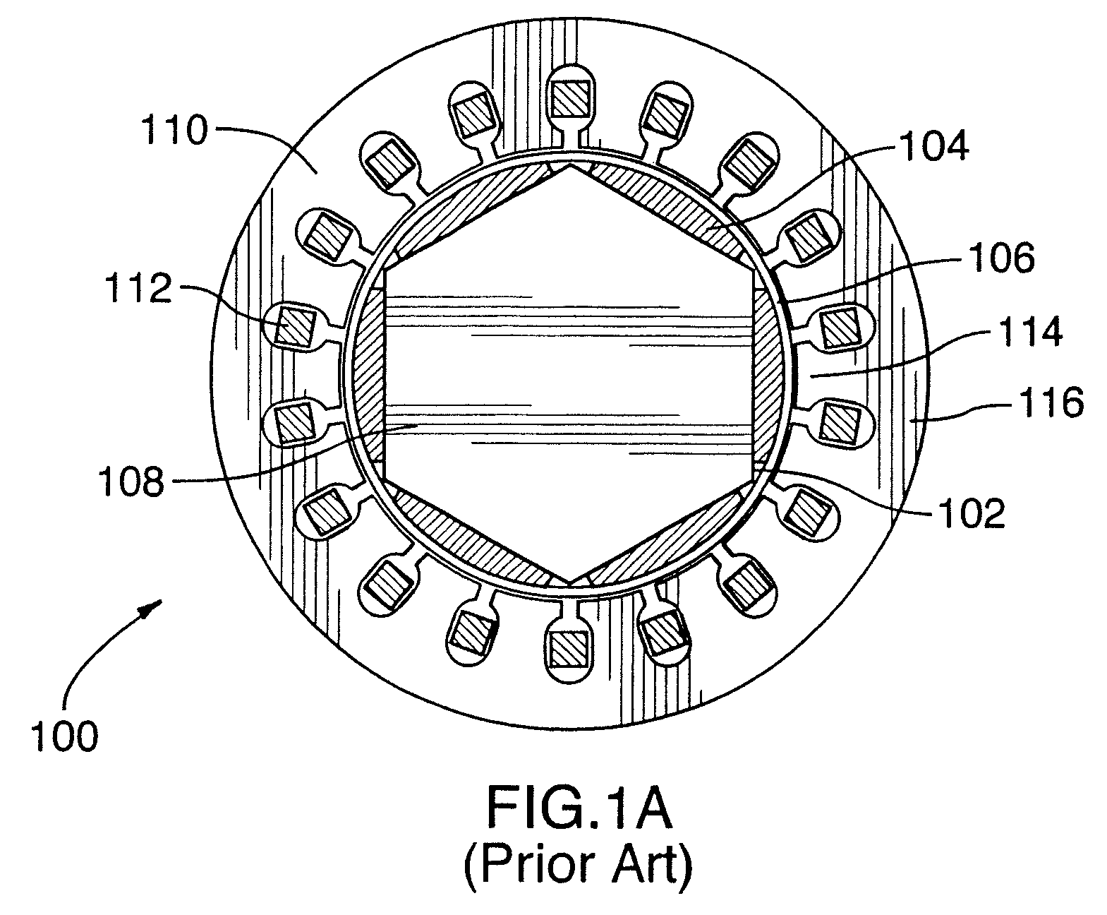
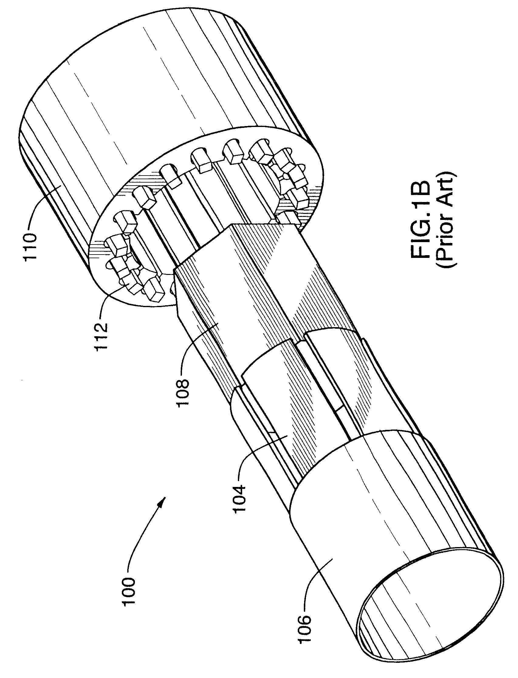
CROSS-REFERENCE TO RELATED U.S. APPLICATIONS[0001]The present application is a divisional of the U.S. patent application Ser. No. 11 / 531,854 filed Sep. 14, 2006, now U.S. Pat. No. 7,312,550, which is a continuation of U.S. patent application Ser. No. 11 / 159,290 filed Jun. 23, 2005, now U.S. Pat. No. 7,126,313, which is a divisional of U.S. patent application Ser. No. 10 / 444,952 filed May 27, 2003, now U.S. Pat. No. 6,965,183, all of which are hereby incorporated by reference.TECHNICAL FIELD[0002]The invention relates to electric machines such as alternators and motors and, more particularly, to a novel architecture for such machines.BACKGROUND OF THE ART[0003]Referring to FIGS. 1A and 1B, a typical permanent magnet (PM) machine according to the prior art is shown at 100. Prior art PM machine 100 has a rotor 102, with permanent magnets 104 mounted thereto by a retaining ring 106, which is mounted on a rotatable shaft 108. Rotor 102 is adjacent a stator 110 having a plurality of windi...

Claims


Application Information

Patent Timeline
Patent Type & Authority Patents(United States)
IPC IPC(8): H02P11/00H02H7/06H02P9/00F01D15/10H02K7/18H02K16/02H02K16/00F02C6/00
CPCH02K1/2786H02K3/12H02K3/16H02K3/28H02K16/04H02K21/22H02P9/02H02K3/46H02P2101/30H02K21/14H02K1/2791
Inventor DOOLEY, KEVIN ALLAN
Owner PRATT & WHITNEY CANADA CORP
Learn More