
Implantable device with reservoirs for increased drug loading

a technology of implantable devices and reservoirs, which is applied in the direction of prosthesis, extracellular fluid disorder, blood vessels, etc., can solve the problems of undesirable reactions, significant proportions of treated vessels re-narrowing or collapsing, and the current drug-loading and drug-delivery characteristics of the method of loading drugs onto the implantable device may be deficien

Inactive Publication Date: 2009-08-18
MEDTRONIC VASCULAR INC
View PDF18 Cites 74 Cited by
  • Summary
  • Abstract
  • Description
  • Claims
  • Application Information

AI Technical Summary

Problems solved by technology

Unfortunately, significant proportions of treated vessels re-narrow or collapse soon after the procedure.
Stent insertion may cause undesirable reactions such as inflammation, infection, thrombosis, and proliferation of cell growth that occludes the passageway.
It has been discovered that methods of loading drugs onto implantable devices may be deficient in their current drug-loading and drug-delivery characteristics.
In particular, the amount or volume of the drug capable of being delivered to the target site may be insufficient due to the limited surface areas on the stent and the control of the rate of elution is limited by the chemical characteristics of the drug.
In addition, during delivery of the stent, any coating exposed to the body lumen can lose a portion of the coating during delivery, either as a result of blood flow over the surface, or by contacting the vessel tissue prior to delivery to the target site.
Furthermore, the use of a polymer matrix to control the release of the drug has been shown to lead to inflammatory response and may be linked to the occurrence of late thrombosis within the stent.
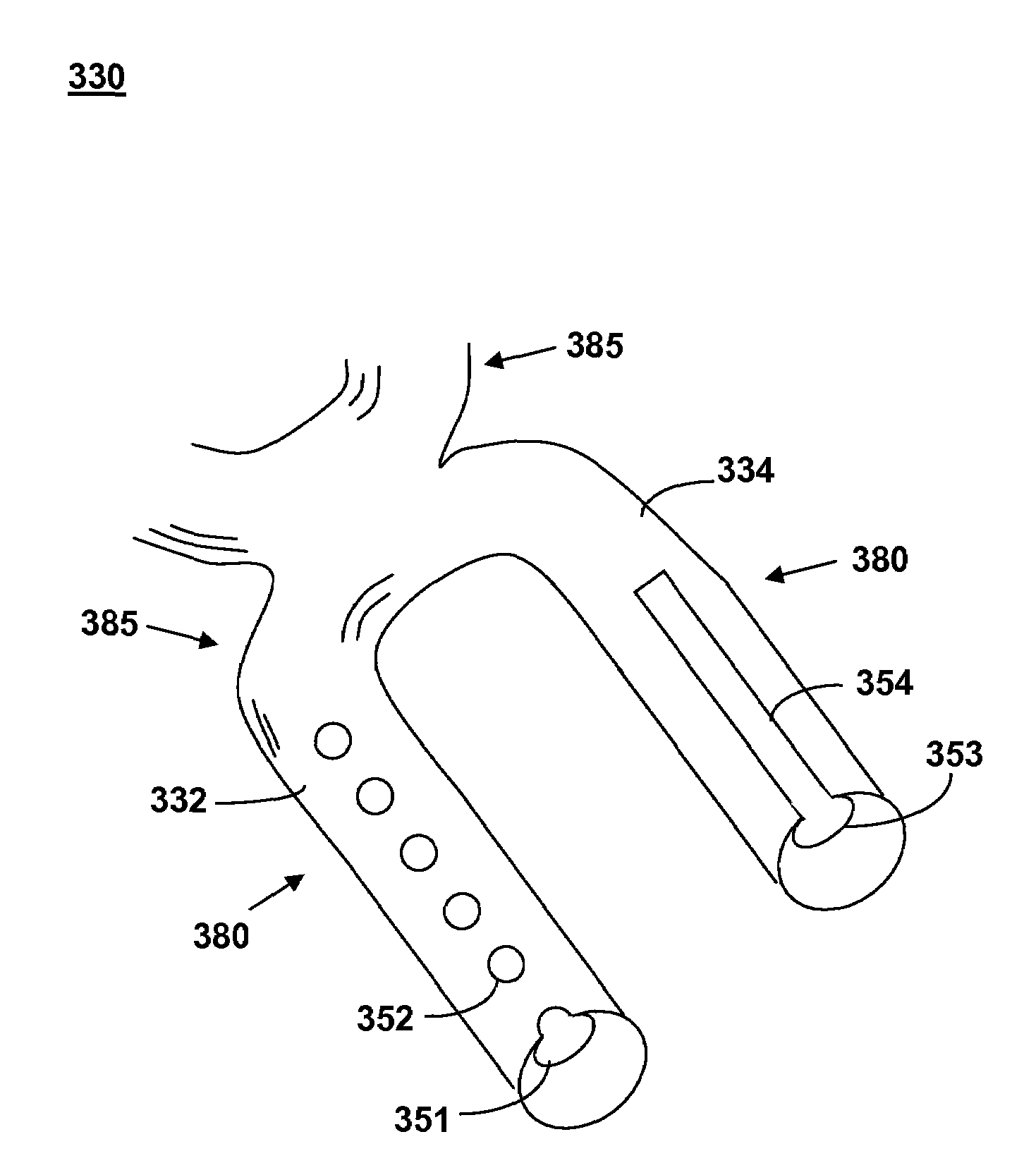
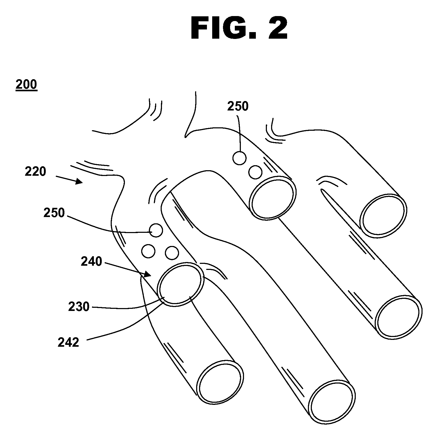
One problem that has arisen with drug reservoirs within implantable devices is that after implantation the rate of release of the drug from the reservoir is hard to control due to the size of the opening through which the drug is released.

Method used


Image

  • Implantable device with reservoirs for increased drug loading
  • Implantable device with reservoirs for increased drug loading
  • Implantable device with reservoirs for increased drug loading

Examples


Embodiment Construction

[0024]The invention will now be described by reference to the drawings wherein like numbers refer to like structures.

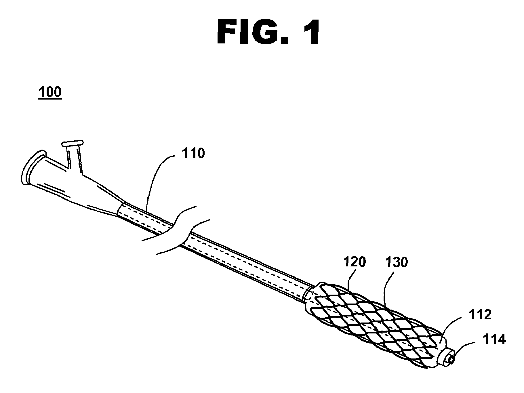
[0025]FIG. 1 shows an illustration of a system for treating a vascular condition, comprising a stent coupled to a catheter, in accordance with one embodiment of the present invention at 100. Stent with catheter 100 includes a stent 120 coupled to a delivery catheter 110. Stent 120 includes a stent framework 130. Stent framework 130 includes a plurality of drug reservoirs disposed within an outer surface of the stent framework. A therapeutic drug is disposed within the drug reservoirs. The drug reservoirs, in one embodiment, are pores. In another embodiment, the drug reservoirs are channels.

[0026]Insertion of stent 120 into a vessel in the body helps treat, for example, heart disease, various cardiovascular ailments, and other vascular conditions. Catheter-deployed stent 120 typically is used to treat one or more blockages, occlusions, stenoses, or diseased regions in ...


PUM

PropertyMeasurementUnit
thickaaaaaaaaaa
thickaaaaaaaaaa
thicknessaaaaaaaaaa

Abstract

A method of manufacturing a drug loaded stent includes applying a photo resistant coating to at least a portion of a stent framework and removing at least a portion of the photo resistant coating from the stent framework. The method further includes applying an etchant to at least a portion of the stent framework and forming a plurality undercut drug reservoirs in the stent framework based on applying the etchant. A stent for treating a vascular condition includes a stent framework, a plurality of undercut reservoirs formed within the stent framework and a therapeutic agent disposed within at least a portion of the plurality of undercut reservoirs.

Description

TECHNICAL FIELD[0001]The technical field of this disclosure is medical implantable device coating methods, particularly, a system and method for providing an implantable device with reservoirs to increase the amount of therapeutic agent loaded into the implantable device.BACKGROUND OF THE INVENTION[0002]Wide ranges of medical treatments have been developed using implantable devices such as endoluminal prostheses, which are medical devices adapted for temporary or permanent implantation within a body lumen, including naturally occurring and artificially made lumens. Examples of lumens in which endoluminal prostheses may be implanted include arteries such as those located within coronary, mesentery, peripheral, or cerebral vasculature; veins; gastrointestinal tract; biliary tract; urethra; trachea; hepatic shunts; and fallopian tubes. Various types of endoluminal prostheses have also been developed with particular structure to modify the mechanics of the targeted luminal wall.[0003]St...

Claims


Application Information

Patent Timeline
Patent Type & Authority Patents(United States)
IPC IPC(8): A61F2/06
CPCA61L31/16A61L31/146A61F2/91A61F2250/0068A61L2400/18A61L2300/61Y10S623/901A61P7/02A61P9/00A61P9/10
Inventor REA, SUSANALLEN, JEFF
Owner MEDTRONIC VASCULAR INC
Learn More